Semi-constrained and mobile-bearing disc prosthesis

a mobile-bearing, semi-constrained technology, applied in the field of artificial disc replacement devices, can solve the problems of increasing the stress on other components, reducing the functional value of the disc,

Inactive Publication Date: 2005-04-21
WARSAW ORTHOPEDIC INC
View PDF37 Cites 99 Cited by
  • Summary
  • Abstract
  • Description
  • Claims
  • Application Information

AI Technical Summary

Problems solved by technology

However, the intervertebral disc often experiences anatomical changes, such as disc degeneration, with advancing age.
The nucleus loses the ability to sustain hydrostatic pressure and deform properly because of water loss and because the annular fibers can no longer maintain tension of its web-like lattice structure.
Narrowing

Method used


Image

  • Semi-constrained and mobile-bearing disc prosthesis
  • Semi-constrained and mobile-bearing disc prosthesis
  • Semi-constrained and mobile-bearing disc prosthesis

Examples


Embodiment Construction

[0023] For the purposes of promoting an understanding of the principles of the invention, references will now be made to the embodiments, or examples, illustrated in the drawings, and specific languages will be used to describe the same. It will nevertheless be understood that no limitation of the scope of the invention is thereby intended. Any alterations and further modifications in the described embodiments, and any further applications of the principles of the invention as described herein are contemplated as would normally occur to one skilled in the art to which the invention relates.

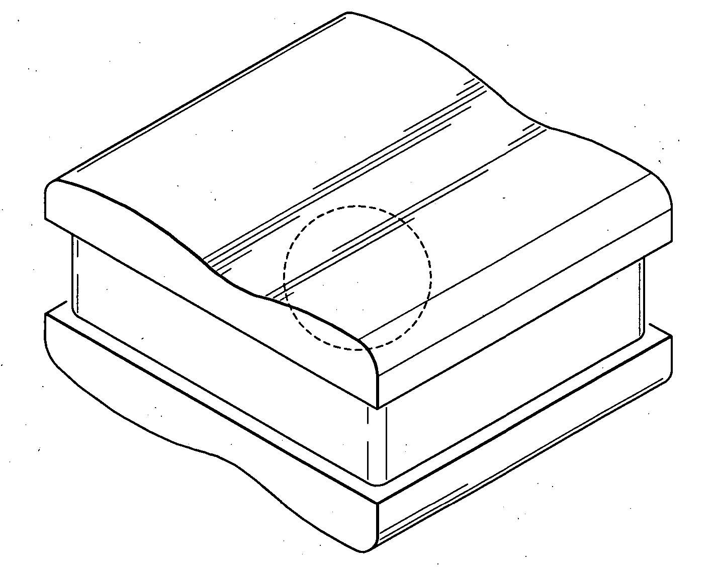
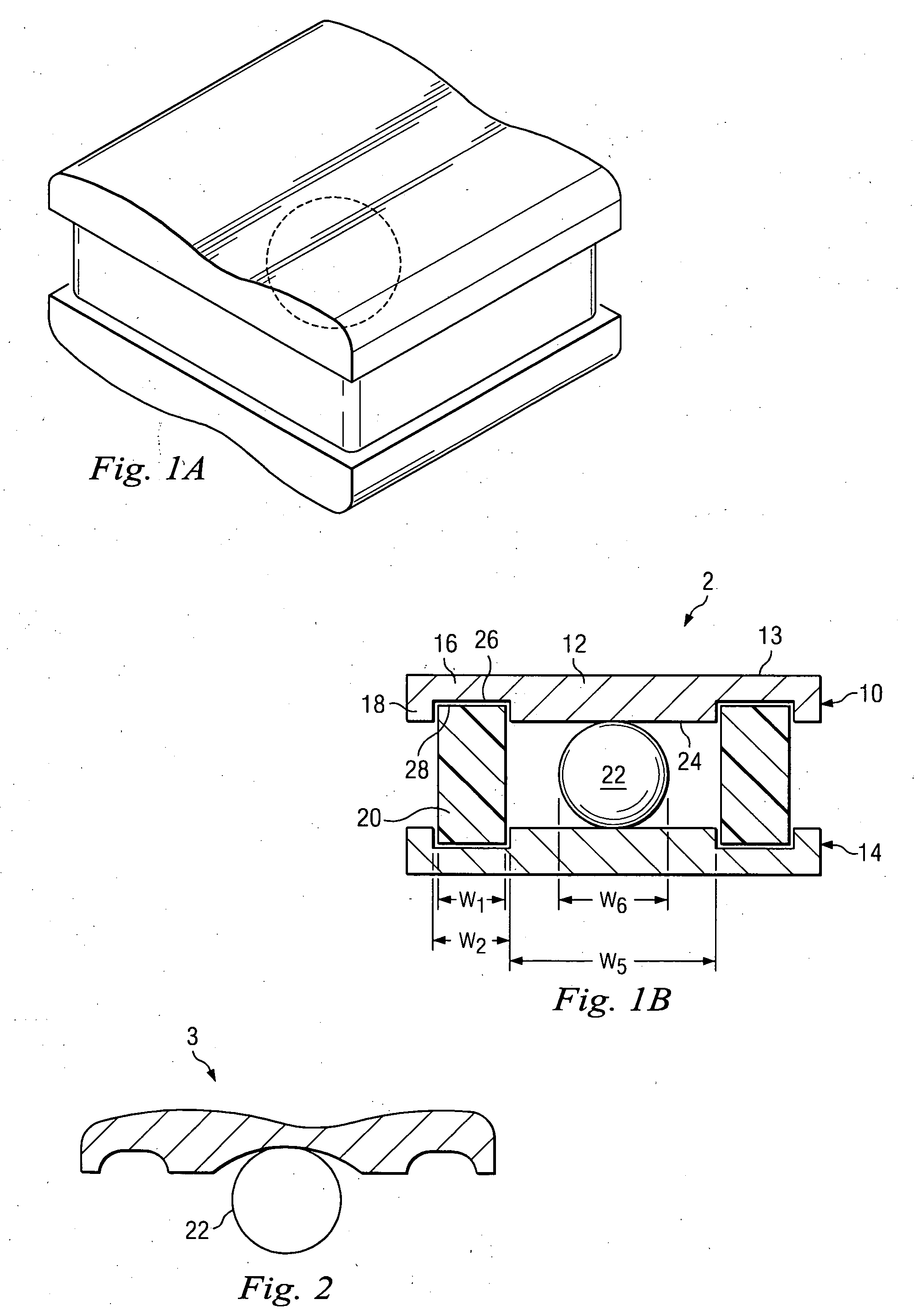
[0024] The present invention provides an improved disc replacement device for replacing a disc in an animal subject. In one example, the present invention takes advantage of the simple and elegant Fernstrom ball, and improves its structure by providing bearing surfaces against the vertebral endplates. In many of the embodiments described below, a single bearing surface is shown. However, it will ...


PUM

PropertyMeasurementUnit
Thicknessaaaaaaaaaa
Flexibilityaaaaaaaaaa
Shape memory effectaaaaaaaaaa

Abstract

A disc replacement device is provided for replacing a spinal disc in an animal subject. The disc replacement device includes a shell, a fulcrum, and a damping sleeve. The shell further comprises a first portion adapted for articulating with the fulcrum such as a spherical stainless steel ball, and a second portion adapted for coupling with the damping sleeve.

Description

FIELD OF THE INVENTION [0001] The present invention relates generally to artificial replacement devices, and more particularly, to artificial disc replacement devices. BACKGROUND [0002] Intervertebral discs are located between the concave articular surfaces of the adjacent vertebral body endplates. They form important and unique articulating systems in the spine, allowing for multiplanar motion. In general, they permit movements such as flexion, extension, lateral flexion, and rotation. [0003] However, the intervertebral disc often experiences anatomical changes, such as disc degeneration, with advancing age. The most significant changes to the disc include: the water and proteoglycan content of the nucleus pulposus decreases; the water proteoglycan content of the annulus decreases, but not the extent of the nucleus; the collagen fibers of the annulus fibrosus become distorted; and tears occur in the lamellae, due in part to distortion of the collagen fibers, one or more of which co...

Claims


Application Information

Patent Timeline
IPC IPC(8): A61F2/00A61F2/30A61F2/44A61F2/46
CPCA61F2/441A61F2310/00029A61F2/4611A61F2002/30242A61F2002/30354A61F2002/30563A61F2002/30662A61F2002/30685A61F2002/30919A61F2002/443A61F2220/0033A61F2230/0071A61F2310/00017A61F2310/00023A61F2/4425A61F2/44
Inventor EISERMANN, LUKAS
Owner WARSAW ORTHOPEDIC INC
Why Eureka
Try Eureka