Separator for clutch

A separation device and clutch technology, applied in the direction of clutches, electric clutches, mechanical drive clutches, etc., can solve problems such as high energy, and achieve the effect of simple length, simple structure, and simple triggering

Inactive Publication Date: 2009-06-17
SCHAEFFLER TECH AG & CO KG
View PDF1 Cites 11 Cited by
  • Summary
  • Abstract
  • Description
  • Claims
  • Application Information

AI Technical Summary

Problems solved by technology

However, this method has the disadvantage that higher energy must be used in order to engage the clutch, i.e. to move the bearing seat in the radial direction inwards

Method used


Image

  • Separator for clutch
  • Separator for clutch
  • Separator for clutch

Examples


Embodiment Construction

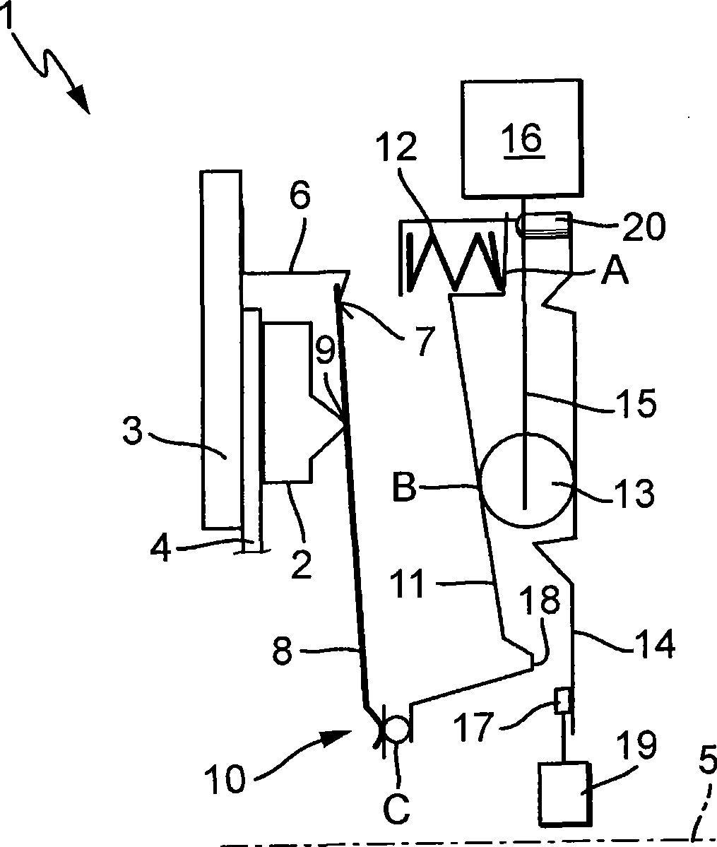
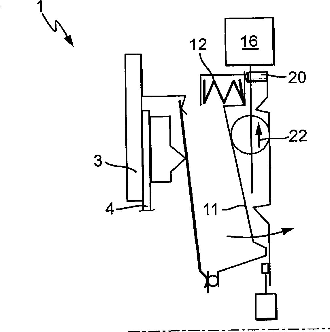
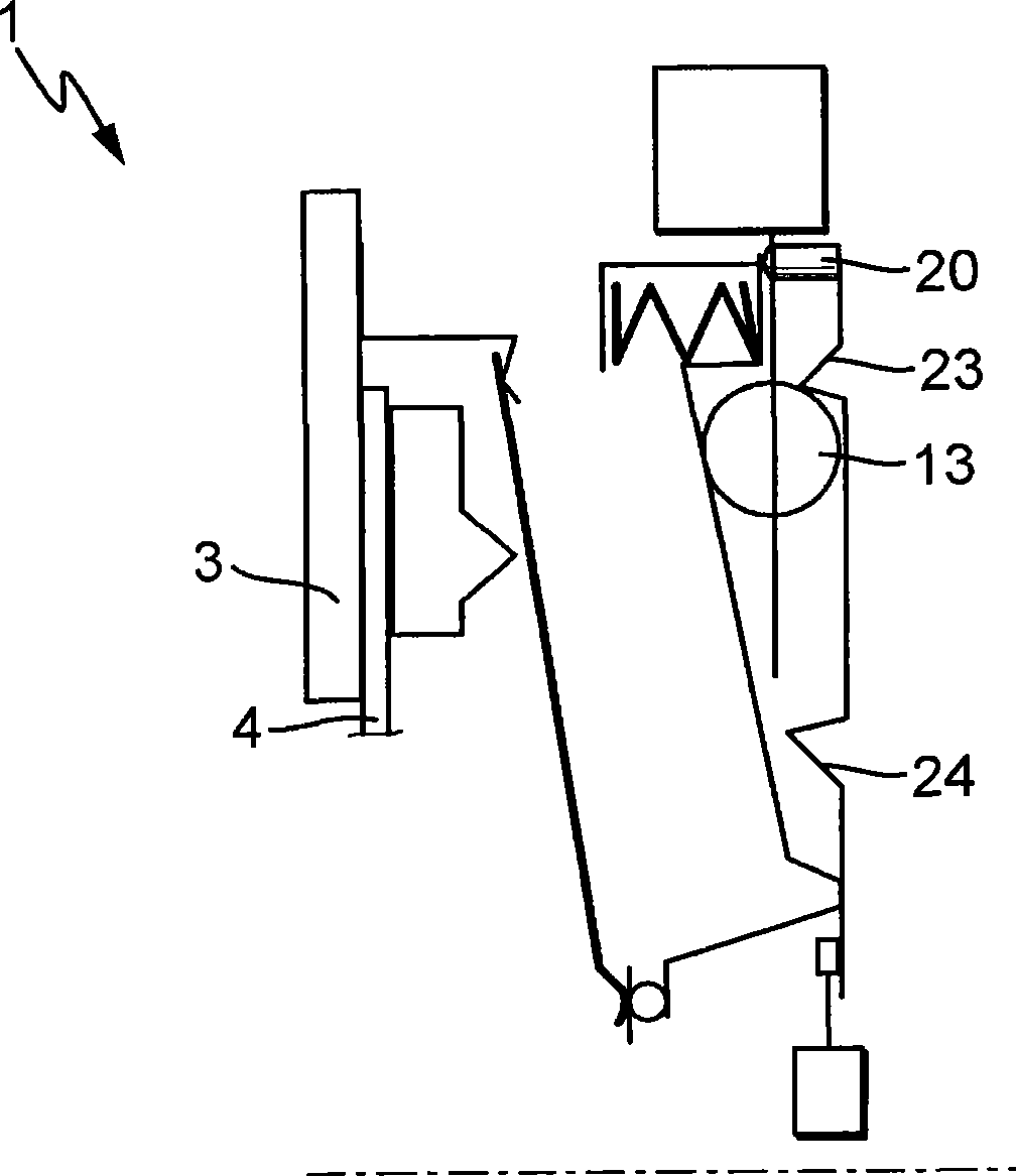
[0024] Figure 1 to Figure 3 A schematic view of a first embodiment of the disconnecting device according to the invention, the so-called rocker lever actuator, is shown. by means of figure 1 The principle structure of an embodiment of the separation device according to the present invention will be described. Although most of the parts or assemblies are rotationally symmetrical with respect to the axis of rotation of the crankshaft or the transmission input shaft, which are not shown in detail here, this representation has been intentionally omitted for reasons of clarity.

[0025] The clutch 1 basically comprises a pressure plate 2 , a counter pressure plate 3 and a clutch disk 4 arranged between the pressure plate 2 and the counter pressure plate 3 . The clutch disc 4 is connected to the transmission input shaft not shown here without relative rotation, and the counter pressure plate 3 is connected to the crankshaft not shown here, and the pressure plate 2 can rotate in t...


PUM


Abstract

The invention relates to a shifting device for operating a clutch with clutch axial line, especially a clutch in a motor vehicle drive unit between a combustion engine and a gear-shifting transmission. The shifting device comprises a shifting lever is rotatably supported at a rotation point relative to radial movement of clutch axial line between an external bearing and internal bearing of the shifting lever and on a mobile bearing seat fixed on a axial direction and moving along the radial direction and the external bearing is elastically mounted with a spring and the internal bearing cooperates with a shifting bearing and moved to a shifting path. The terminal position lies on the mobile conversion stop position when the clutch is at disconnection state and better reset of the bearing block is realized in the clutch. A path of the external bearing is limited in an effective direction of the spring by a stop such that a force is exerted on a bearing block at the rotary point by the shifting lever and the force is suitable for shifting the bearing block in a direction of the external bearing.

Description

technical field [0001] The invention relates to a release device for operating a clutch. Background technique [0002] This disengaging device is also known as a rocker lever actuator. DE 10 2004 009 832 A1 discloses a rocker lever actuator which has some of the features of the preamble of claim 1 . Furthermore, rocker lever actuators of the type described have a switchover stop whose position determines the end position of the release lever or the rocker lever in the disengaged state of the clutch. This is used to trigger the self-compensating adjustment of the displacement-controlled self-compensating clutch, wherein a disengagement travel that is not exceeded during normal operation must be exceeded for the compensating adjustment. The compensation adjustment of the clutch is activated by exceeding the defined disengagement travel. [0003] To actuate the clutch, a bearing seat arranged "underneath" the release lever is moved in a radial direction with respect to the c...

Claims


Application Information

Patent Timeline
Patent Type & Authority Applications(China)
IPC IPC(8): F16D23/12
CPCF16D23/12F16D2023/126F16D28/00
Inventor D·布克哈特
Owner SCHAEFFLER TECH AG & CO KG
Why Eureka
Try Eureka