Testing device

Inactive Publication Date: 2005-04-21
VIA TECH INC
View PDF4 Cites 9 Cited by
  • Summary
  • Abstract
  • Description
  • Claims
  • Application Information

AI Technical Summary

Benefits of technology

[0007] It is therefore a primary object of the present invention is to provide a testing device that uses only one CPU connected with peripheral devices to be test

Problems solved by technology

If the computer determines that it fails, the testing will not pass.
However, the testing procedure requires at least one personal

Method used


Image

  • Testing device
  • Testing device
  • Testing device

Examples


Embodiment Construction

[0012] The structural features and the effects to be achieved may further be understood and appreciated by reference to the presently preferred embodiments together with the detailed description.

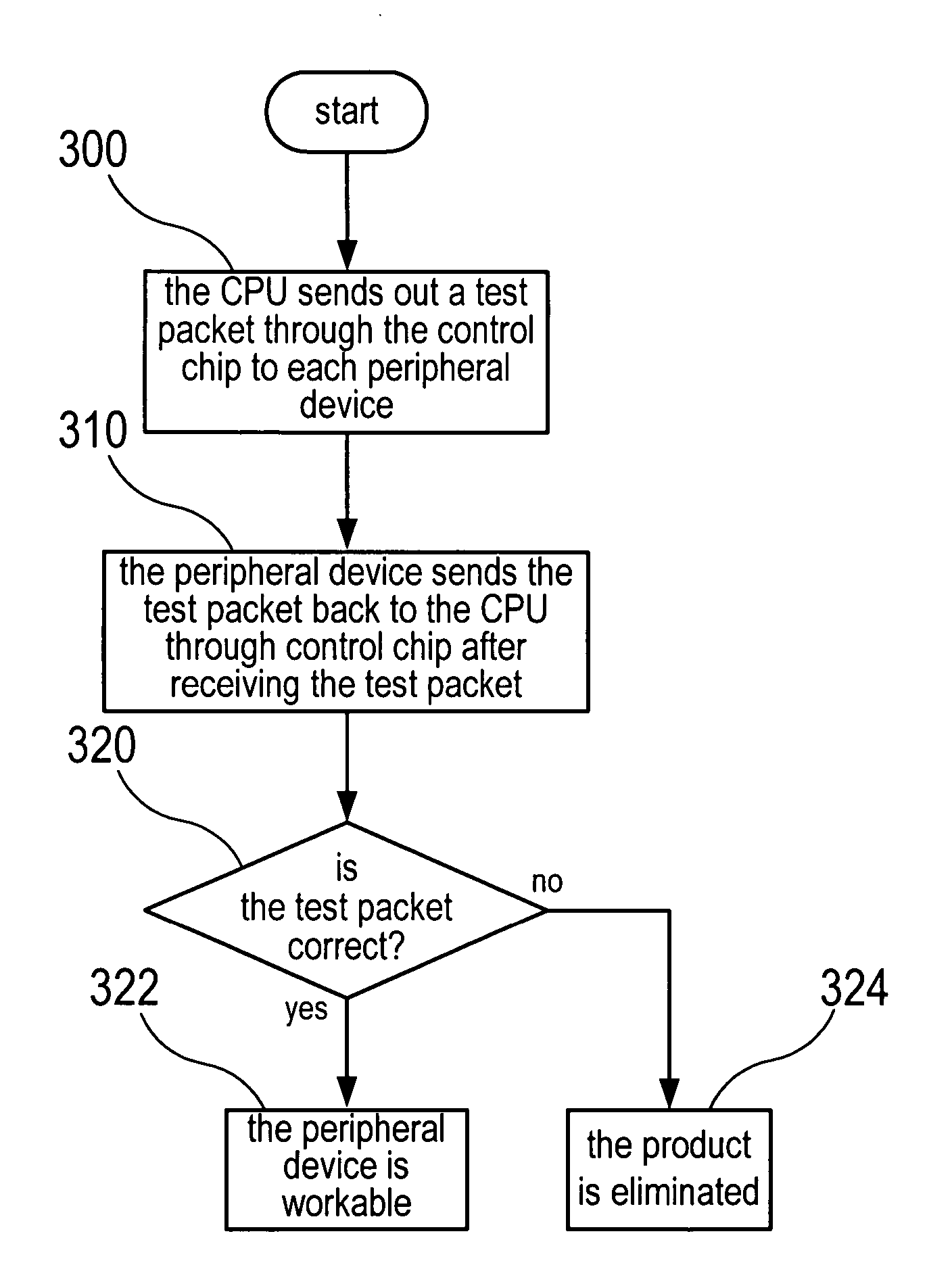
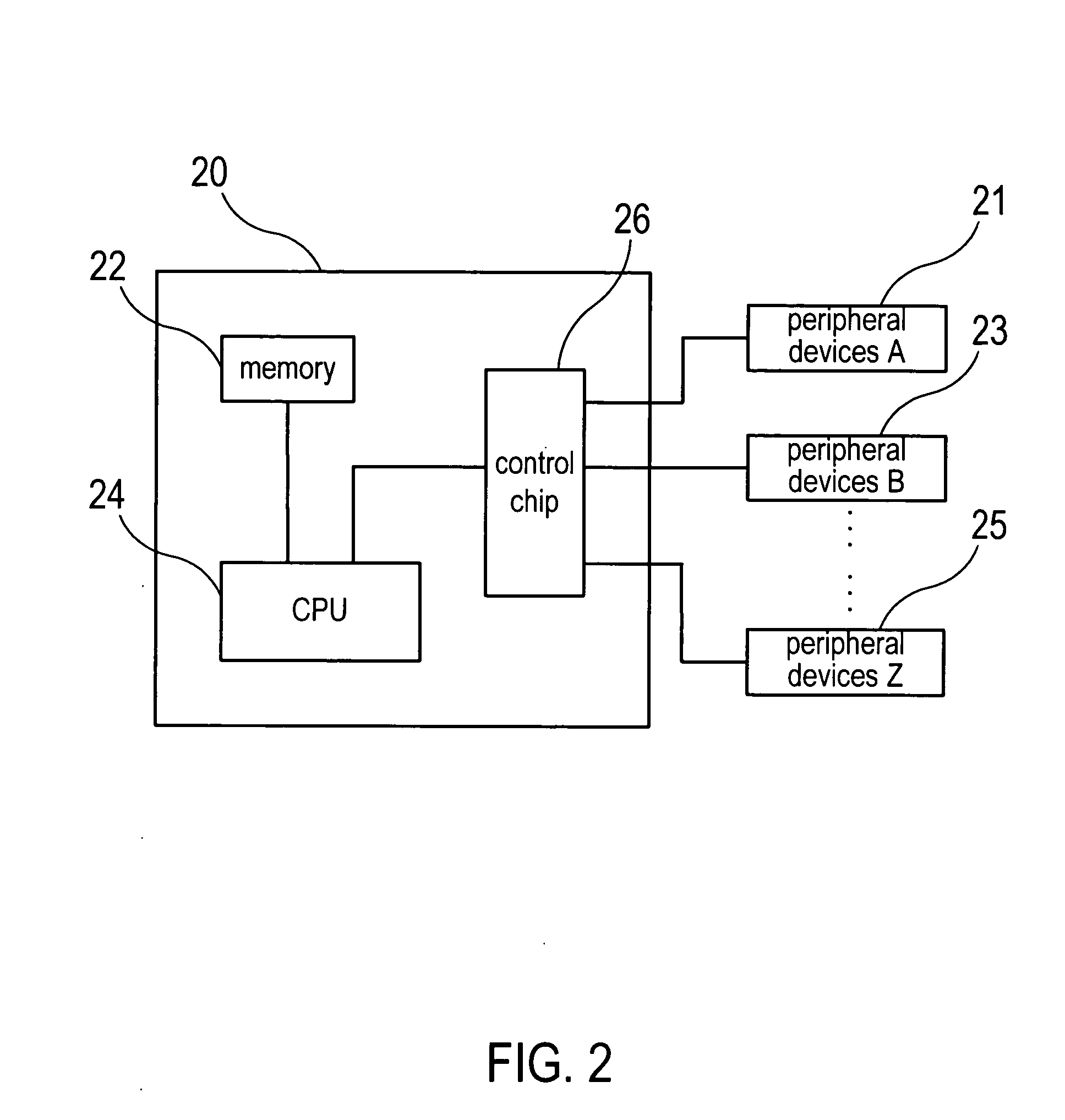
[0013] FIGS. 2&FIG. 3 are respectively a block diagram of a testing device and a test flow chart of a preferred embodiment of the present invention. As shown in figures, a testing device 20 includes a CPU 24, a control chip 26, a memory 22 and a plurality of peripheral devices A 21, B 23 and Z 25 to be tested. The control chip 26 is used for controlling USB interface. The memory 22 is used for storing programs and data and connected to the CPU 24 to be accessed by the CPU 24. The peripheral devices A 21, B 23 and Z 25 to be tested are connected to the control chip 26. Each peripheral device is provided with USB interface so that the CPU 24 could test each peripheral device through the control chip 26.

[0014] The memory 22 has a predetermined test packet and a firmware program to provide the...


PUM


Abstract

A testing device for testing computer peripheral devices with Universal Serial Bus (USB) is provided. The testing device includes a CPU, a memory with a predetermined firmware program inside, which is connected to the CPU, a control chip with USB interface, which is connected to the CPU and is provided with a plurality of connecting ports for connecting with peripheral devices to be tested. The firmware program inside the memory is used for controlling the CPU to test the peripheral devices to be tested through the control chipset. According to one CPU and each peripheral device connected through by a control chip with USB interface for processing test procedures only, the hardware could be more simpler and efficiency.

Description

FIELD OF THE INVENTION [0001] The present invention is related to a testing device, particularly to a testing device for testing peripheral devices provided with USB interface. BACKGROUND OF THE INVENTION [0002] In current computer system, USB interface is used frequently and widely, mostly in the usage of computer peripheral devices. As a result, when peripheral devices with USB interface are produced in factories, they have to be tested before shipping. [0003] Recently, the method of testing the peripheral devices with USB interface uses a personal computer installed with a USB control card for testing. FIG. 1 is a block diagram of conventional testing peripheral devices with USB interface. As shown in FIG. 1, a computer 10 is installed with a USB interface control card 12. Besides, peripheral devices 14&16 to be tested are connected to the USB interface control card 12. The peripheral devices 14&16 could be different kinds of peripheral devices with USB interface such as a mouse,...

Claims


Application Information

Patent Timeline
IPC IPC(8): G06F11/00
CPCG06F11/2221
Inventor HUANG, HC
Owner VIA TECH INC
Why Eureka
Try Eureka