
Workpiece holder for clean container

a technology for workingpieces and containers, applied in the direction of tray containers, transportation and packaging, packaging goods types, etc., can solve the problems of wafer contamination and particle contamination, and achieve the effect of preventing friction and well protecting against contamination

Inactive Publication Date: 2005-04-28
IND TECH RES INST
View PDF0 Cites 1 Cited by
  • Summary
  • Abstract
  • Description
  • Claims
  • Application Information

AI Technical Summary

Benefits of technology

[0007] The present invention has been accomplished under the circumstances in view. It is the main object of the present invention to provide a workpiece holder for clean container, which uses a linking mechanism to prevent the occurrence of friction and the production of particles when covering the housing of the clean container, keeping the workpieces well protected against contamination.
[0011] When stopping the bottom side of the vertical slide against the top side of the base of the clean container, the vertical slide is contacted with the base in a specific point, the vertical slide does not displace relative to the base, therefore no friction is produced between the vertical slide and the base. Because no friction is produced between the vertical slide and the base, no particles are produced when covering the housing to set workpieces into position in the cassette, workpieces are well protected in the clean container against contamination.

Problems solved by technology

According to this design, a friction is produced between the slide and the base when the base pushing the slide, and such friction causes particles that may contaminate loaded wafers.
Except the aforesaid wafer container, some other clean containers for carrying photo masks, glass substrates, and other workpieces may have the same problem.

Method used


Image

  • Workpiece holder for clean container
  • Workpiece holder for clean container
  • Workpiece holder for clean container

Examples


Embodiment Construction

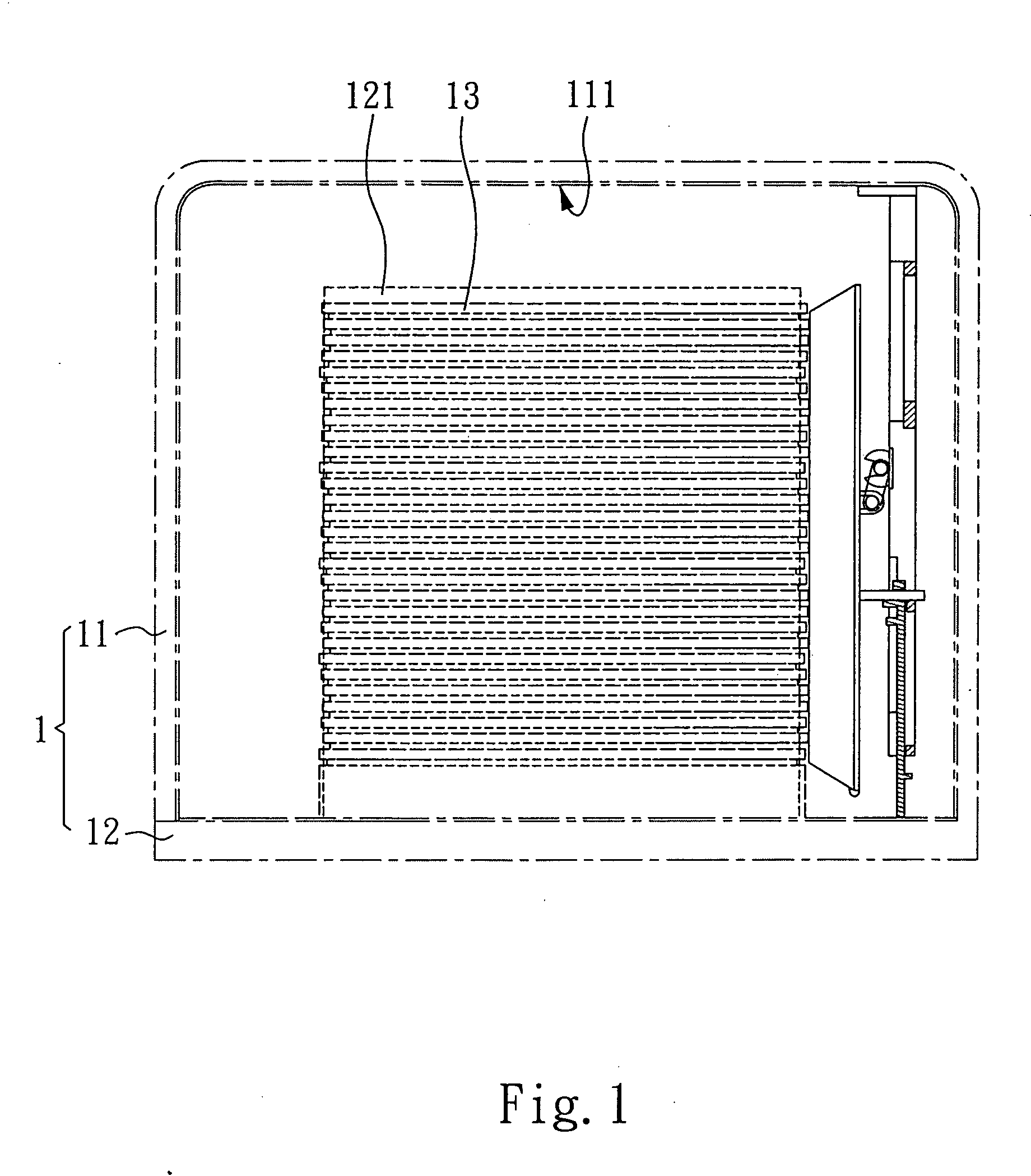
[0018] Referring to FIG. 1, a clean container (for example, a SMIF FOUP) 1 is shown comprising a base 12, a cassette 121 fixedly provided at the top side of the base 12 and holding a plurality of wafers (workpieces) 13 that are transversely inserted into the cassette 121, and a housing 11 covering the base 12 over the cassette 121.

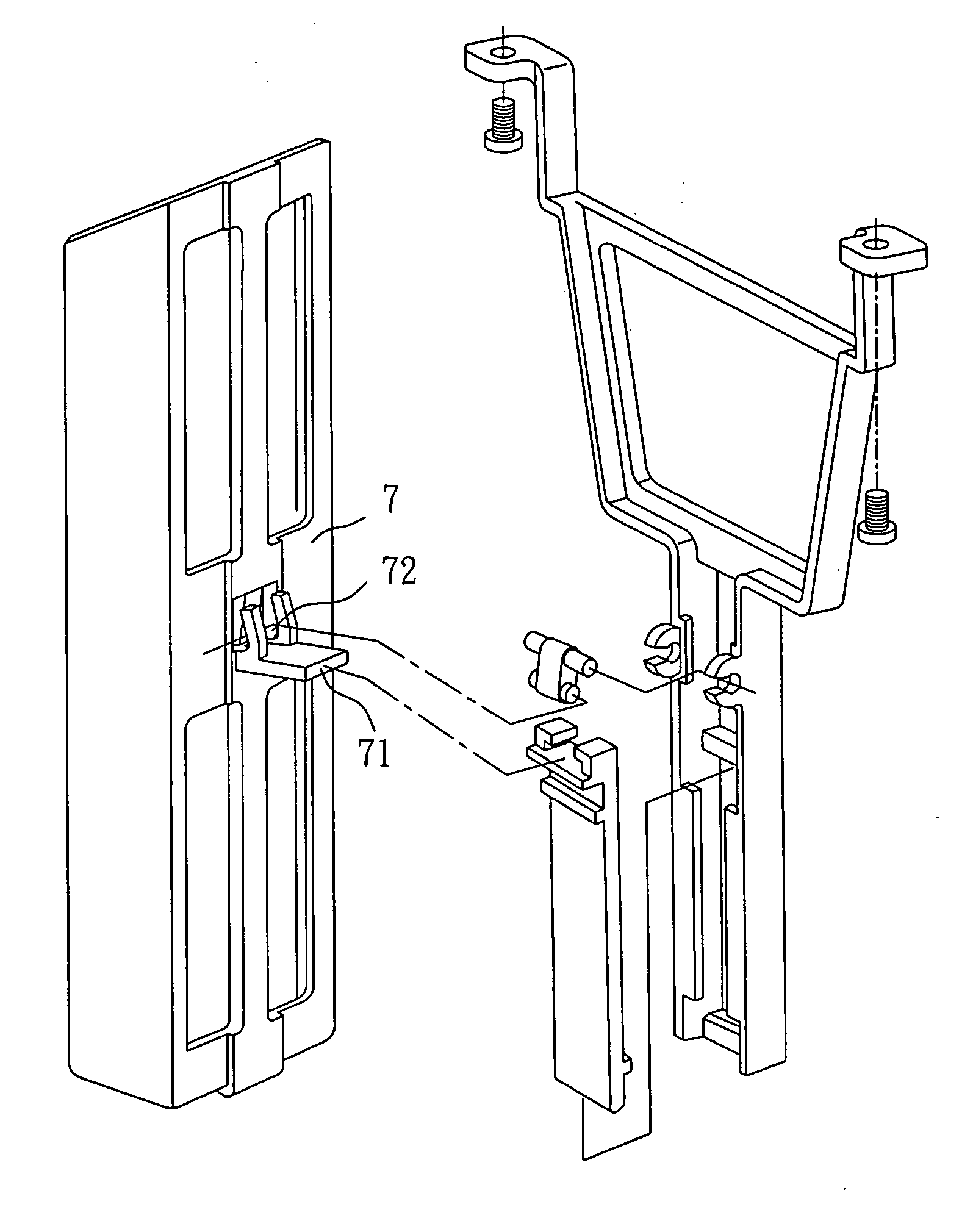
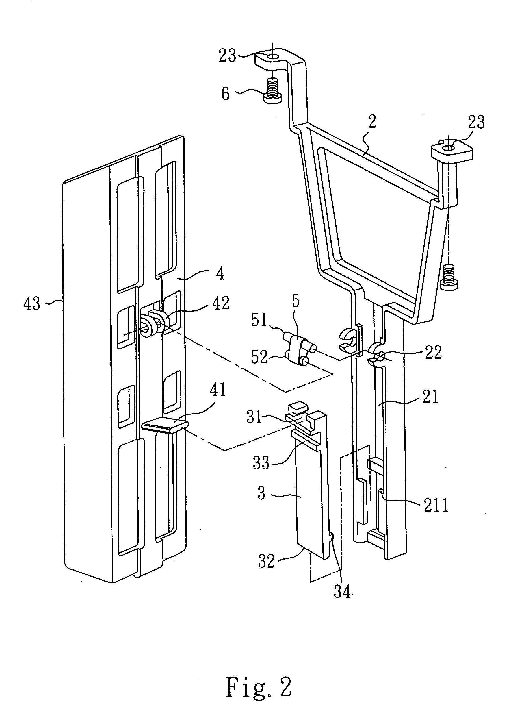
[0019] Referring to FIG. 2 and FIG. 1 again, the workpiece holder used in the aforesaid clean container 1 is comprised of a locating member 2, a vertical slide. 3, a holder member 4, and a link 5. The locating member 2 is fixedly fastened to the inside wall 111 of the housing 11 of the clean container 1. According to this embodiment, the locating member 2 has two mounting holes 23 bilaterally disposed at the top side thereof and fastened to the inside wall 111 of the housing 11 of the clean container 1 with two screws 6 respectively. The locating member 2 having a vertical sliding groove 21, and horizontal knuckles 22 horizontally disposed in front of the...


PUM


Abstract

A workpiece holder is provided inside a clean container such that when covering a housing of the clean container on a base of the clean container, the vertical slide of the workpiece holder is stopped at the base, and a locating member is continuously lowered with the housing, thereby causing the vertical slide to slide upwardly along the locating member and to turn a link, and then causing a holder member to be driven by the link to force a thrust face against workpieces, and therefore the workpieces are pushed into position in a cassette on the base. Because the vertical slide does not displace relative to the base when covering the housing on the base, neither friction nor particles are produced, and workpieces are well protected against contamination.

Description

BACKGROUND OF THE INVENTION [0001] 1. Field of the Invention [0002] The present invention relates to a workpiece holder for clean container and, more particularly to such a workpiece holder, which is practical for use in a clean container to hold workpieces horizontally in position. [0003] 2. Description of Related Art [0004] In semiconductor foundries, produced wafers are horizontally arranged in a cassette, which has supporting flanges for holding a number of wafers in horizontal. The cassette can be mounted on the base of a wafer container, for example, a POD or FOUP, and then covered by the housing of the wafer container for transfer. The housing protects wafers against contamination. [0005] When carrying the wafers in the cassette inside the wafer container, wafers may displace during transfer of the wafer container. In order to eliminate this problem, a positioning structure is used in the wafer container. When covering the housing of the wafer container on the cassette on the...

Claims


Application Information

Patent Timeline
Patent Type & Authority Applications(United States)
IPC IPC(8): B65D85/30H01L21/673H01L21/68
CPCH01L21/67369
Inventor PAI, WEI-MINGCHEN, DAR-ZENLEE, JYH-JONEWU, TZONG-MINGLIN, HUI-CHIH
Owner IND TECH RES INST
Learn More