Three jet island fluidic oscillator

a fluidic oscillator and jet island technology, applied in the field of fluid handling processes and apparatus, can solve the problems of inability to provide the desired spray pattern of known fluidic oscillators, and considerable difficulties, and achieve the effect of high viscosity

Active Publication Date: 2005-04-28
DLHBOWLES INC
View PDF27 Cites 31 Cited by
  • Summary
  • Abstract
  • Description
  • Claims
  • Application Information

AI Technical Summary

Benefits of technology

[0011] There has been summarized above, rather broadly, the prior art that is related to the present invention in order that the context of the present invention may be better understood and appreciated. In this regard, it is instructive to also consider the objects and advantages of the present invention.
[0012] It is an object of the present invention to provide new, improved fluidic oscillators and fluid flow methods that are capable of generating oscillating, fluid jets with spatially uniform droplet distributions over a wide range of operating temperatures.
[0013] It is another object of the present invention to provide improved fluidic oscillators and fluid flow methods that are capable of generating oscillating, fluid jets with high viscosity liquids.
[0014] It is yet another object of the pres

Problems solved by technology

However, the flow from such a fluidic oscillator is characterized by having the swept jet, that issues from it, dwell on the end positions of its sweep such that its downstream distribution of droplets, which impact upon a plane that is perpendicular to the direction of the spray, is heavy ended as characterized by a larger volume of the liquid being collected at the two ends of the distribution.
Considerab

Method used


Image

  • Three jet island fluidic oscillator
  • Three jet island fluidic oscillator
  • Three jet island fluidic oscillator

Examples


Embodiment Construction

[0036] Before explaining at least one embodiment of the present invention in detail, it is to be understood that the invention is not limited in its application to the details of construction and to the arrangements of the components set forth in the following description or illustrated in the drawings. The invention is capable of other embodiments and of being practiced and carried out in various ways.

[0037] Also, it is to be understood that the phraseology and terminology employed herein are for the purpose of description and should not be regarded as limiting. For example, the discussion herein below generally relates to liquid spray techniques; however, it should be apparent that the inventive concepts described herein are applicable also to the dispersal of other fluids, including gases, fluidized solid particles, etc.

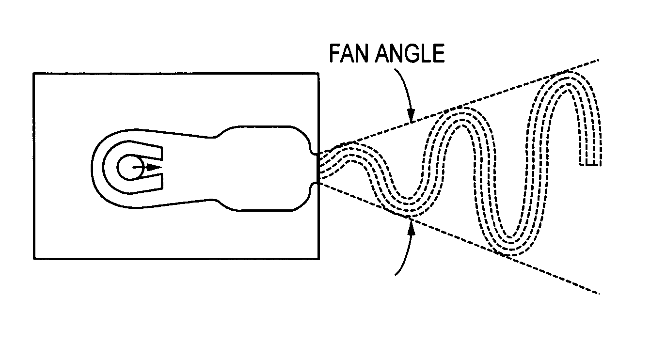
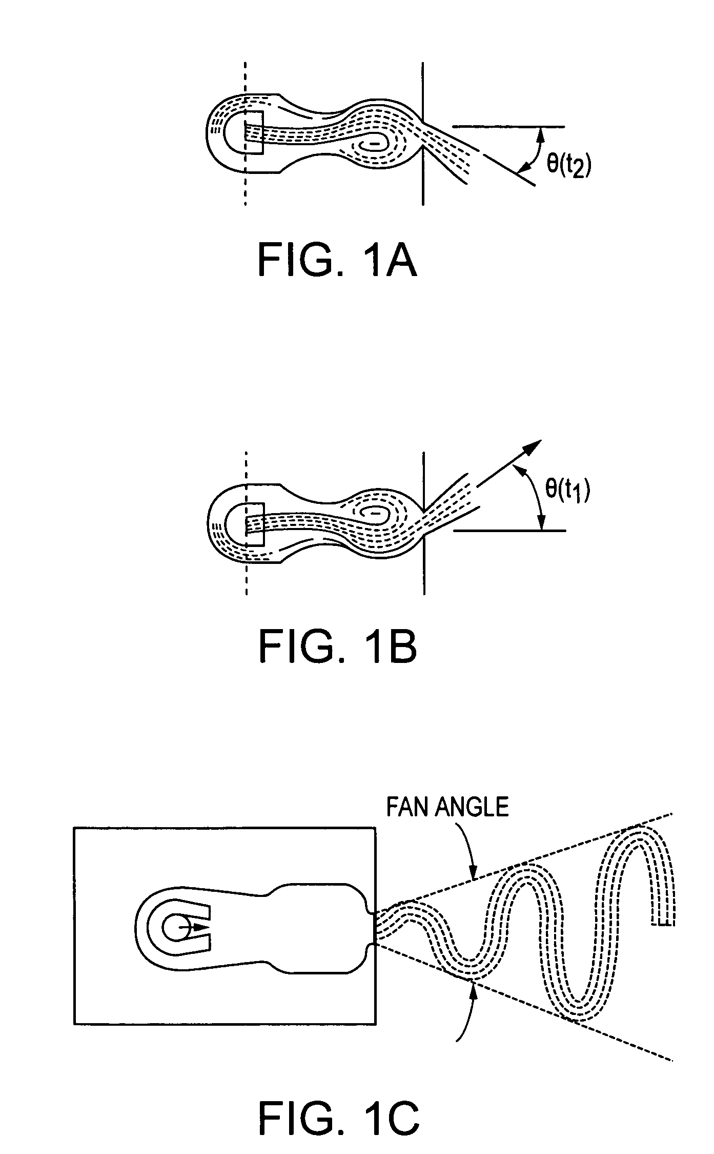
[0038] The present invention involves methods for creating fluidic oscillators of the type that are suitable for generating oscillating, fluid jets having very ...


PUM


Abstract

A fluidic oscillator suitable for use at colder temperatures for utilizing a pressurized liquid to generate a uniform spatial distribution of droplets has (a) an inlet for the pressurized liquid, (b) a set of three power nozzles that are fed by the pressurized liquid, (c) an interaction chamber attached to the nozzles and which receives the flow from the nozzles, wherein this chamber has an upstream and a downstream portion, with the upstream portion having a pair of boundary edges and a longitudinal centerline that is approximately equally spaced between the edges, and wherein one of the power nozzles is directed along the chamber's longitudinal centerline, (d) a throat from which the liquid exhausts from the interaction chamber, and (e) an island located in the interaction chamber, with this island being situated downstream of the power nozzle that is directed along the chamber's longitudinal centerline. In a preferred embodiment, this oscillator is further configured such that: (i) one of the power nozzles is located proximate each of the chamber's boundary edges, (ii) its nozzles are configured to accelerate the movement of the liquid that flows through the nozzles, (iii) its throat has right and left sidewalls that diverge downstream, and (iv) the power nozzles and island are oriented and scaled such as to generate flow vortices behind the island that are swept out of the throat in a manner such that these vortices flow alternately proximate the throat's right sidewall and then its left sidewall.

Description

CROSS-REFERENCE TO RELATED APPLICATION [0001] This application claims the benefit of U.S. Provisional Patent Application No. 60 / 515,068, filed Oct. 21, 2003 by Shridhar Gopalan.BACKGROUND OF THE INVENTION [0002] 1. Field of the Invention [0003] This invention relates to fluid handling processes and apparatus. More particularly, this invention relates to a fluidic oscillator that can control the spraying of high viscosity fluids so that such sprays are uniformly distributed over their target areas. [0004] 2. Description of the Related Art [0005] Fluidic oscillators are well known in the prior art for their ability to provide a wide range of liquid spray patterns by cyclically deflecting a liquid jet. The operation of most fluidic oscillators is characterized by the cyclic deflection of a fluid jet without the use of mechanical moving parts. Consequently, an advantage of fluidic oscillators is that they are not subject to the wear and tear which adversely affects the reliability and o...

Claims


Application Information

Patent Timeline
IPC IPC(8): B05B1/00B05B1/08B05B1/34B60S1/52F23D11/38
CPCB05B1/08B60S1/52B05B1/34Y10S239/03Y10T137/2104Y10T137/2185
Inventor GOPALAN, SHRIDHAR
Owner DLHBOWLES INC
Why Eureka
Try Eureka