Battery protection circuit

Inactive Publication Date: 2005-04-28
TELEFON AB LM ERICSSON (PUBL)
View PDF19 Cites 21 Cited by
  • Summary
  • Abstract
  • Description
  • Claims
  • Application Information

AI Technical Summary

Benefits of technology

[0017] As mentioned, the invention further relates to a method of protecting a battery from over discharge, said battery being connected through a controlled switch to an electric load under control of control circuitry, said controlled switch having a first state in which a connection is provided from the battery to the load, and wherein the load is disconnected from the battery by bringing the controlled switch to a second state. When the method compris

Problems solved by technology

However, these batteries need safety electronics to protect them from being overcharged and over-discharged.
However, the power control circuit itself, which is still connected to the battery, has a certain leakage current, and therefore the battery will continue to be discharged by this leakage current even after the load has been disconnected.
Sooner or later this will lead to over-discharge of the battery.
Due to its own leakage current this power control circuit is not sufficient to prevent the battery from being over-discharged.
Similar circuits are known from U.S. Pat. No. 5,729,061 and EP 458 716, and these circuits suffer

Method used


Image

  • Battery protection circuit
  • Battery protection circuit
  • Battery protection circuit

Examples


Example

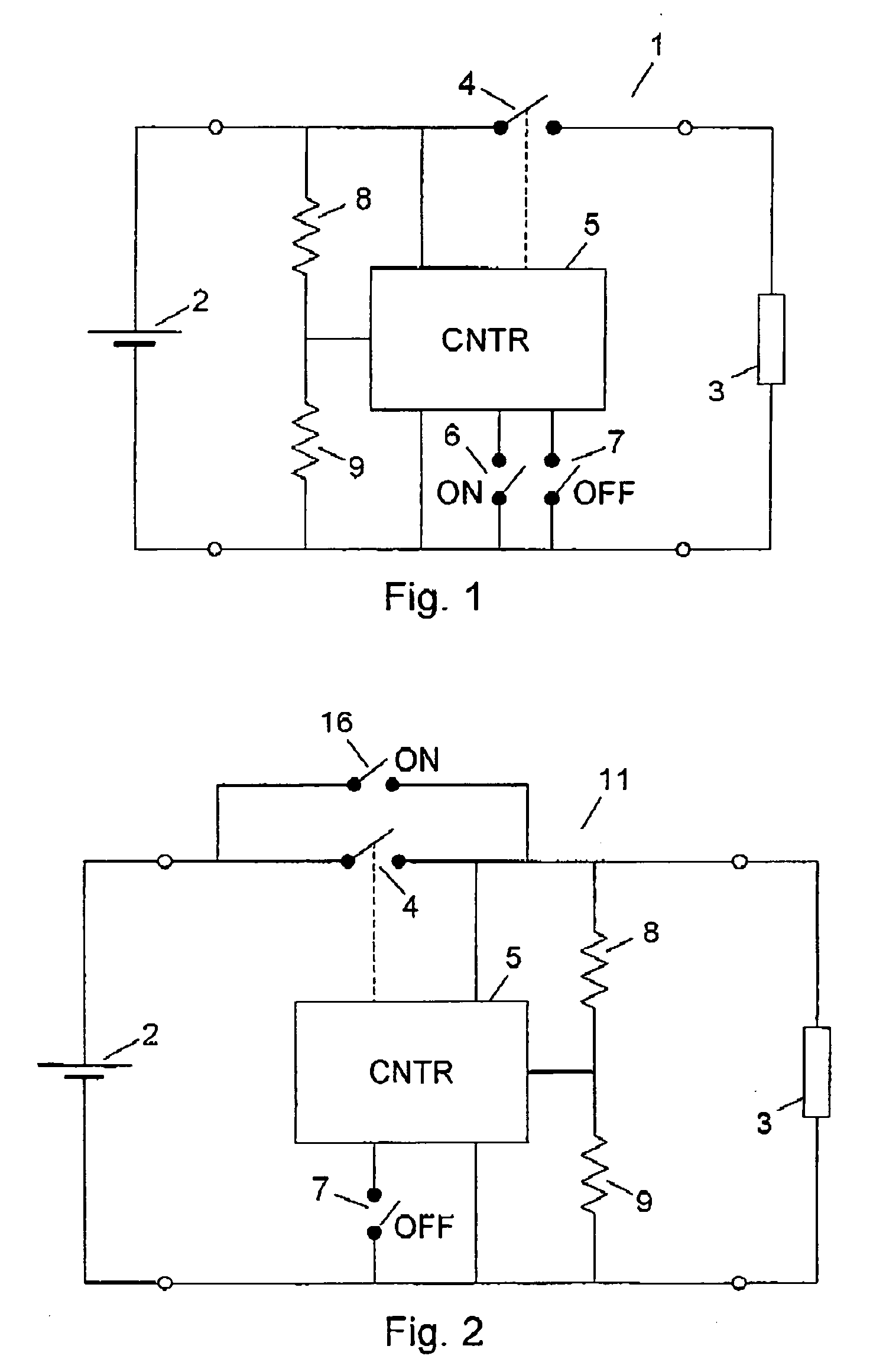
[0027]FIG. 1 shows an example of a known control system 1 for a battery 2. The battery 2 could, as an example, be a Li-ion or Li-polymer battery, and it is arranged for supplying power to a load 3, which represents an electronic device, such as a computer, a mobile telephone, or a camcorder. A controlled switch 4 connects and disconnects the battery 2 to and from the load 3, and it is controlled by the control circuit 5. Two manually operated switches 6 and 7 are used for switching the controlled switch 4 on and off. An activation of the “on” switch 6 causes the control circuit 5 to close the controlled switch 4 so that power is supplied from the battery 2 to the load 3. Correspondingly, an activation of the “off” switch 7 causes the control circuit 5 to open the controlled switch 4 so that the battery 2 is disconnected from the load 3. The switches 6 and 7 may also be combined to one “on / off” switch.

[0028] Resistors 8 and 9 form a voltage divider providing an input voltage to the ...


PUM


Abstract

A power supply arrangement for supplying power from a battery (2) to an electric load (3) comprises a controlled switch (4) having a first state in which a connection is provided from the battery (2) to the load (3), and a second state in which the load (3) is disconnected from the battery (2), and a control circuit (5, 8, 9) for controlling the state of the controlled switch (4). The control circuit (5, 8, 9) is arranged to be disconnected from the battery (2) when the controlled switch (4) is in its second state. By disconnecting not only the electrical load, but also the control circuit from the battery, it is ensured that this circuit cannot draw any leakage current from the battery, when the load is switched off. This means that no over-discharge protection is needed in the battery itself.

Description

TECHNICAL FIELD OF THE INVENTION [0001] The invention relates to a power supply arrangement for supplying power from a battery to an electric load, said arrangement comprising a controlled switch having a first state in which a connection is provided from the battery to the load, and a second state in which the load is disconnected from the battery; and control circuitry for controlling the state of the controlled switch, The invention further relates to a method of protecting a battery from over discharge. DESCRIPTION OF RELATED ART [0002] Many portable electronic devices, such as laptop computers, mobile tell phones or camcorders, are powered by rechargeable batteries, either as the only power source or as a back-up for power supplies connected to main power lines. [0003] Such batteries or battery packs are to an increasing degree based on lithium-ion (Li-ion) or lithium-polymer (Li-polymer) cells due to their overall superior performance characteristics, such as a higher energy d...

Claims


Application Information

Patent Timeline
IPC IPC(8): H02J7/00
CPCH02J7/0031
Inventor SVENSSON, JAN-OLOFWOLF, MATS ERIK
Owner TELEFON AB LM ERICSSON (PUBL)
Why Eureka
Try Eureka