Ethernet passive optical network ring and its method of authorization and collision detection

a technology of optical network ring and authorization, applied in the direction of transmission monitoring, frequency-division multiplex, wavelength-division multiplex system, etc., can solve the problems of system breakage, increased cost, and increased complexity of control, and achieve the effect of reducing collisions

Inactive Publication Date: 2005-04-28
IND TECH RES INST
View PDF3 Cites 26 Cited by
  • Summary
  • Abstract
  • Description
  • Claims
  • Application Information

AI Technical Summary

Benefits of technology

[0010] Using the disclosed structure, one can determine the location of a user from the difference between the two times a signal is transmitted from an ONU to the two ends of the OLT, thereby verifying the user's identity...

Problems solved by technology

Due to intrinsic defects, the system breaks as the optical ring 10 fails.
However, the switching method increases device costs ...

Method used


Image

  • Ethernet passive optical network ring and its method of authorization and collision detection
  • Ethernet passive optical network ring and its method of authorization and collision detection
  • Ethernet passive optical network ring and its method of authorization and collision detection

Examples


Embodiment Construction

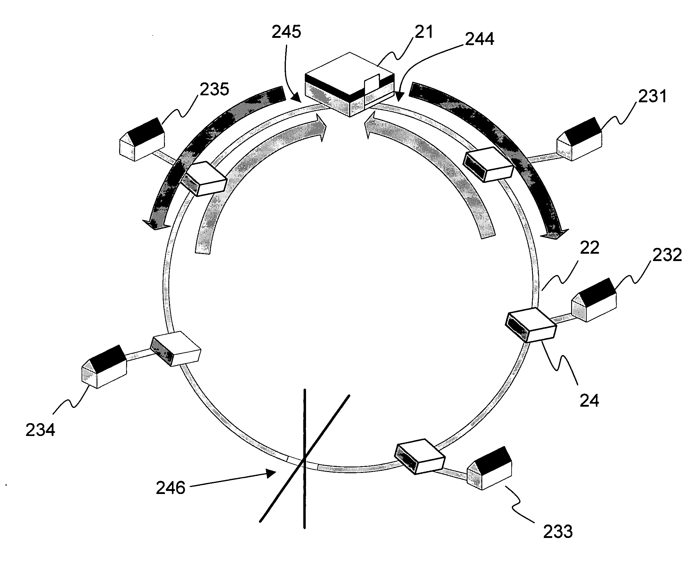
[0024] In view of the drawbacks in the conventional Ethernet passive optical network ring, the invention uses a two-way transmission structure to guarantee that the downstream network still has a connection with the optical line termination (OLT) 11 even if the network has a failure. Moreover, it avoids the use of the switching method introduced in the prior art. The invention can directly perform two-way transmissions without the introduction of any new type of active or passive optical devices.

[0025] As shown in FIG. 5, the invention mainly utilizes a three-port passive optical splitting module 24 at the intersection of an optical network unit (ONU) 23 and the optical ring 22. The three-port passive optical splitting module 24 has three ports (the first port 221, the second port 222, and the third port 223 shown in the drawing) to connect the ONU 23 and the optical ring 22. The three-port passive optical splitting module 24 uses three passages (the first passage 241, the second p...


PUM


Abstract

An Ethernet passive optical network (EPON) ring for providing protection against fiber failures. The optical network unit (ONU) is coupled to the ring fiber by a three-port passive optical splitting module that has three two-way optical passages. By the three two-way optical passages, the OUN receives/transmits data from/to the two ends of the optical line termination (OLT) to provide protection while the fiber failure. Moreover, it provides better authorization of users and simpler collision detection by the two-way transmission of the three-port passive optical splitting module to prevent hackers from invading and to reduce collisions.

Description

BACKGROUND OF THE INVENTION [0001] 1. Field of Invention [0002] The invention relates to an Ethernet passive optical network ring used in a local optical network system. In particular, the invention relates to an Ethernet passive optical network ring that can prevent the whole system from breaking when the network ring fails without the need of additional active or passive optical devices in any form. [0003] 2. Related Art [0004] The structure of a normal Ethernet passive optical network (EPON) ring is shown in FIG. 1. It uses an optical line termination (OLT) 11 to manage several optical network units (ONU) 12. The two ends of an optical ring 10 are connected to the OLT 11. Each of the ONU 12 uses an optical splitter 13 to connect to the optical ring 10. Therefore, controlled by the OLT 11, they can receive / transmit data. Such an optical network structure is usually suitable for systems with low-density users. [0005] Due to intrinsic defects, the system breaks as the optical ring 1...

Claims


Application Information

Patent Timeline
IPC IPC(8): G01R31/08H04L12/26H04L12/42
CPCH04J14/0227H04J14/0283H04J14/0294H04Q2011/0092H04L12/42H04Q11/0067H04Q2011/0081H04J14/0297
Inventor YANG, TZU-JIANLIN, KUAN-MINGTSENG, YEN-PINWANG, JA-NANLIU, JEFFREY
Owner IND TECH RES INST
Why Eureka
Try Eureka