
System and method for channel-adaptive antenna selection

Inactive Publication Date: 2005-04-28
AVAGO TECH WIRELESS IP SINGAPORE PTE
View PDF17 Cites 125 Cited by
  • Summary
  • Abstract
  • Description
  • Claims
  • Application Information

AI Technical Summary

Benefits of technology

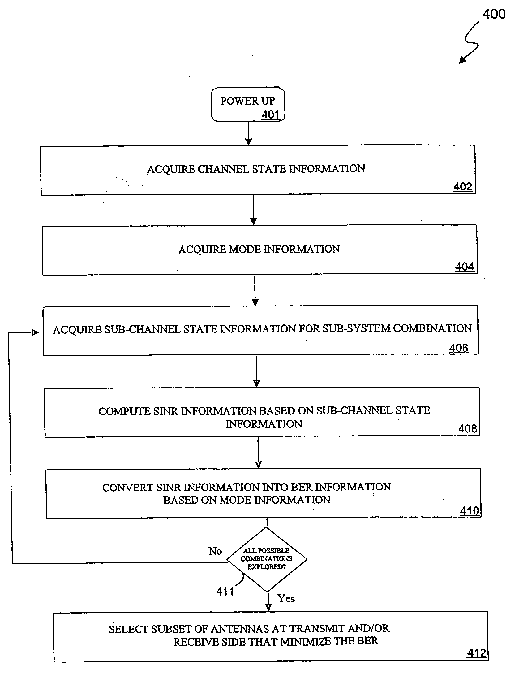
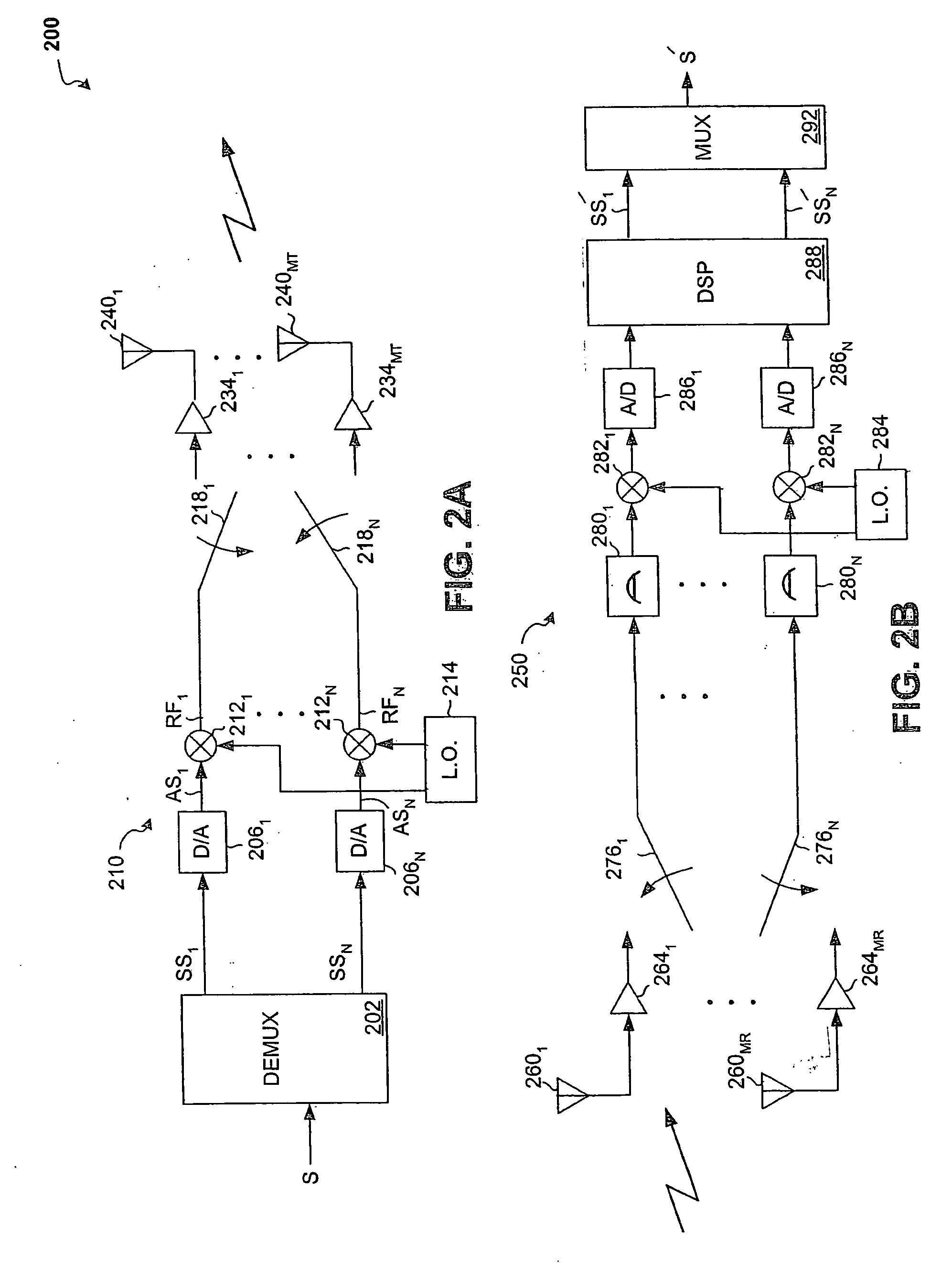
[0014] In one embodiment according to some aspects of the present invention, a system that selects N antenna elements in an M-antenna-element transmitter or an M-antenna-element receiver, in which N is less than M, may include, for example, M antenna elements in the M-antenna-element transmitter or the M-antenna-element receiver, N RF chains, and a switch coupled to the N RF chains. The M-antenna-element receiver may compute an output bit error rate for each possible N antenna element subset of the M antenna elements. Each output bit error may be computed based on at least one set of channel parameter statistics. The M-antenna-element receiver may select the particular N antenna element subset based on a criterion predicated on the computed output bit error rates. In response to the selection of the particular N antenna element subset based on the criterion, the switch may couple the N RF chains to the N antenna elements of the particular N antenna element subset.
[0015] In another embodiment according to some aspects of the present invention, a method that selects a subset of receive antennas of a receiver to receive a transmitted RF signal may include, for example, one or more of the following: establishing possible subsets of the receive antennas; determining sets of channel parameter statistics corresponding to the possible subsets of the receive antennas; computing output bit error rates of the receiver, each output bit error rate being computed based on at least one set of channel parameter statistics; selecting a particular possible subset of the receive antennas based upon a criterion predicated on the computed output bit error rates; and connecting one or more RF chains of the receiver to the receive antennas of the selected particular possible subset.
[0016] In another embodiment according to some aspects of the present invention, a method that selects a subset of transmit antennas of a transmitter to transmit an RF input signal as a plurality of RF output signals that are subsequently received by a receiver, may include, for example, one or more of the following: establishing possible subsets of the transmit antennas; determining sets of channel parameter statistics corresponding to the possible subsets of the transmit antennas; selecting transmission modes respectively corresponding to the sets of channel parameter statistics; computing output bit error rates of the receiver, each output bit error rate being computed based on at least one set of channel parameter statistics and at least one selected transmission mode; selecting a particular possible subset of the transmit antennas based on a criterion predicated on at least the computed output bit error rates; and connecting one or more RF chains of the transmitter to the transmit antennas of the selected particular possible subset.
[0017] In yet another embodiment according to some aspects of the present invention, in a communication system including a transmitter and a receiver, the transmitter including transmit antennas adapted to transmit a set

Problems solved by technology

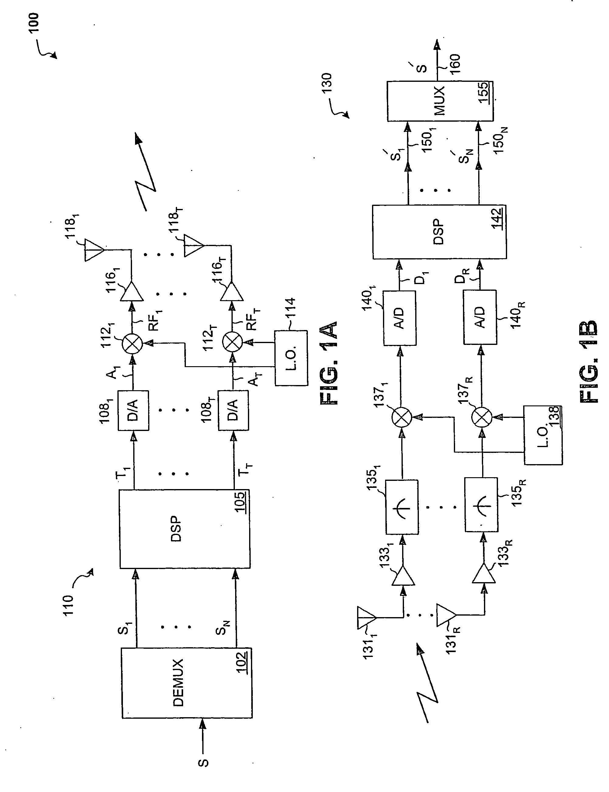
Although increasing the number of transmit and / or receive antennas enhances various aspects of the performance of MIMO systems, the provision of a separate RF chain for each transmit and receive antenna increases costs.
It is thus apparent that as the number of transmit and receive antennas increases, overall system cost and power consumption may dramatically increase.
However, capacity is an idealized quantity that may be an unachievable bound because it may necessitate perfect coding and / or equalization and / or continuous modulation.
In practice, the equalizer is not ideal, limited coding (or even no coding) and quantized modulation is used.

Method used


Image

  • System and method for channel-adaptive antenna selection
  • System and method for channel-adaptive antenna selection
  • System and method for channel-adaptive antenna selection

Examples


Embodiment Construction

I. Overview of Some Aspects of the Present Invention

[0027] Some embodiments according to some aspects of the present invention may relate to communication systems that use a transmitter and / or a receiver that have multiple antenna elements.

[0028] Some embodiments according to some aspects of the present invention may relate to systems and methods that provide channel-adaptive antenna selection in multi-antenna-element communication systems.

[0029] Some embodiments according to some aspects of the present invention may be implemented to facilitate a selection of a subset of antenna elements in one or more multi-antenna wireless communication devices based on a criterion predicated, at least in part, on computed output bit error rates.

[0030] Some embodiments according to some aspects of the present invention may be implemented to facilitate the selection of a subset of antenna elements in one or more multi-antenna wireless communication devices so as to minimize or to optimize, for ...


PUM


Abstract

Systems and methods that provide channel-adaptive antenna selection in multi-antenna-element communication systems are provided. In one embodiment, a method that selects a subset of receive antennas of a receiver to receive a transmitted RF signal may include, for example, one or more of the following: establishing possible subsets of the receive antennas; determining sets of channel parameter statistics corresponding to the possible subsets of the receive antennas; computing output bit error rates of the receiver, each output bit error rate being computed based on at least one set of channel parameter statistics; selecting a particular possible subset of the receive antennas based upon a criterion predicated on the computed output bit error rates; and connecting one or more RF chains of the receiver to the receive antennas of the selected particular possible subset.

Description

RELATED APPLICATIONS [0001] This application is a continuation-in-part of U.S. patent application Ser. No. 10 / 957,398, entitled “System and Method for Antenna Selection” and filed Oct. 1, 2004, which claims priority to and claims benefit from U.S. patent application Ser. No. 60 / 507,843, entitled “Antenna Selection Method in Multi-Antenna Communication Systems Based On Minimum Bit Error Rate” and filed Oct. 1, 2003. This application also makes reference to the above-mentioned applications. [0002] This application makes reference to, claims priority to and claims benefit from U.S. Patent Application Ser. No. 60 / 519,398, entitled “Channel-Adaptive Antenna Selection Method Based Upon Minimization of Bit Error Rate” and filed Nov. 12, 2003. [0003] The above-identified patent applications are hereby incorporated herein by reference in their entirety.FEDERALLY SPONSORED RESEARCH OR DEVELOPMENT [0004] [Not Applicable]MICROFICHE / COPYRIGHT REFERENCE [0005] [Not Applicable]BACKGROUND OF THE IN...

Claims


Application Information

Patent Timeline
IPC IPC(8): H04B7/06H04B7/08H04L1/06
CPCH04B7/061H04B7/0691H04B7/0697H04B7/0808H04B7/0814H01R13/6599H04B7/0874H04L1/0618H04B1/02H04B1/06H01R13/521H04B7/082
Inventor CATREUX-ERCEG, SEVERINEERCEG, VINKOROUX, PIETERROOYEN, PIETER VANWINTERS, JACK
Owner AVAGO TECH WIRELESS IP SINGAPORE PTE
Learn More