Method of creating a virtual network topology for use in a graphical user interface

a virtual network and user interface technology, applied in the field of communication networks, can solve problems such as intermittent transmission of signals

Inactive Publication Date: 2005-04-28
FINISAR
View PDF6 Cites 51 Cited by
  • Summary
  • Abstract
  • Description
  • Claims
  • Application Information

AI Technical Summary

Benefits of technology

[0010] Briefly summarized, embodiments of the present invention are directed to systems and methods by which a software application can depict, for viewing and manipulation, a virtual representation of a network, a portion of a network, or a group of network components. Embodiments of the present invention are implemented within a network communications environment by a software application that operates in conjunction with one or mo

Problems solved by technology

Within these networks, transmission

Method used


Image

  • Method of creating a virtual network topology for use in a graphical user interface
  • Method of creating a virtual network topology for use in a graphical user interface
  • Method of creating a virtual network topology for use in a graphical user interface

Examples


Embodiment Construction

[0019] Reference will now be made to figures wherein like structures will be provided with like reference designations. It is understood that the drawings are diagrammatic and schematic representations of exemplary embodiments of the invention, and are not limiting of the present invention nor are they necessarily drawn to scale.

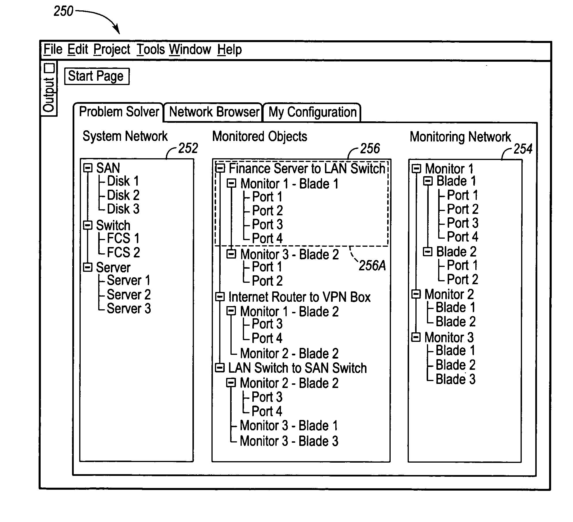
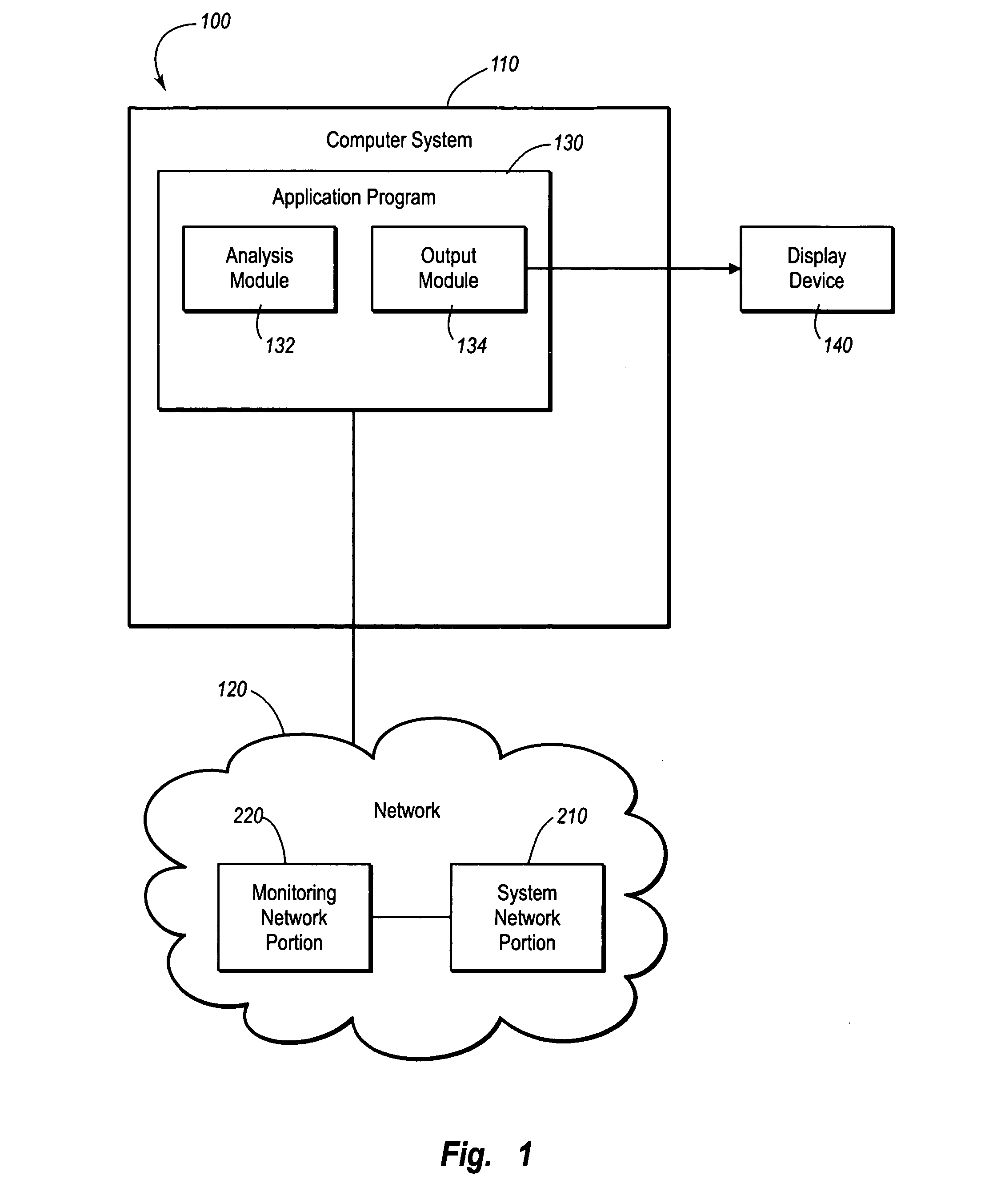
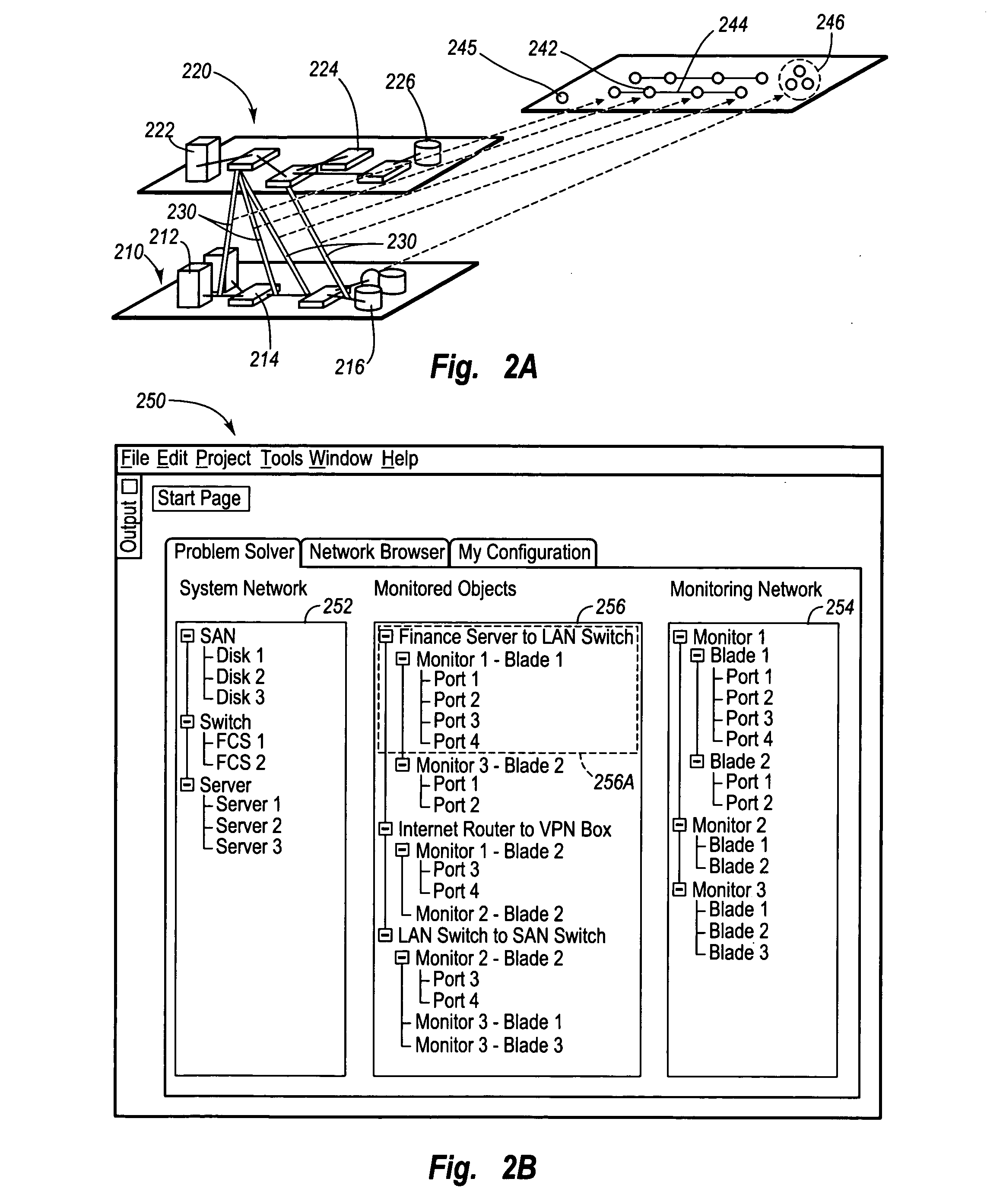
[0020]FIGS. 1-5 depict various features of embodiments of the present invention, which is generally directed to a graphical user interface (“GUI”) representation of a virtual topology of a communication network environment, and methods to achieve such a virtual representation. The virtual network topology as depicted by the GUI can be presented via a screen display or other visual display apparatus. In contrast to other known application-based network GUIs, the virtual network topology GUI depicts not purely physical aspects the network, its components, and relationships between components, but rather displays logical connections between network components....


PUM


Abstract

A method of graphically depicting various network elements of a communications network in a virtual network topology via a graphical user interface (“GUI”) is disclosed. The virtual network topology depicts logical relationships between network components instead of merely depicting physical network component relationships. A system network subset and a monitoring network subset of the communications network are defined according to one layer N of the open system interconnection (“OSI”) layer model. Various logical links are established between the system network and the monitoring network. A virtual topology is defined that depicts the various logical links according to another OSI layer M. The virtual topology is displayed via a GUI that enables modification of the logical links to occur.

Description

CROSS-REFERENCE TO RELATED APPLICATIONS [0001] This application claims the benefit of U.S. Provisional Patent Application No. 60 / 502,021, filed on Sep. 11, 2003, entitled “VIRTUAL NETWORK TOPOLOGY AS GRAPHICAL USER INTERFACE,” which is incorporated herein by reference in its entirety.BACKGROUND [0002] 1. Technology Field [0003] The present invention generally relates to communications networks. In particular, the present invention is directed to methods of creating and graphically displaying virtual network topologies within a communications network in order to facilitate the manipulation thereof. [0004] 2. The Related Technology [0005] Modem computer networks involve the transmission of large amounts of data at very high speeds across the networks. For example, in some networks, transmission rates as high as 10 Gbits / second are currently being used. Today, hardware and protocols that will support transmission rates up to 40 Gbits / second are being developed. Within these networks, t...

Claims


Application Information

Patent Timeline
IPC IPC(8): G06F15/173H04L12/24H04L12/26
CPCH04L41/12H04L41/22H04L41/122
Inventor BERNSTEIN, DAVID R.LAGUISMA, RODRIGO A.
Owner FINISAR
Why Eureka
Try Eureka