
Method of manufacturing an article having a radio frequency identification (RFID) device

a radio frequency identification and manufacturing method technology, applied in the direction of manufacturing tools, metal working apparatus, instruments, etc., can solve the problems of not disclosing an adequate means of retaining the rfid device, potentially damaging the rfid device, and failing to disclose an adequate means of incorporating the rfid device into the label or card

Inactive Publication Date: 2005-05-05
SAXON
View PDF89 Cites 55 Cited by
  • Summary
  • Abstract
  • Description
  • Claims
  • Application Information

AI Technical Summary

Benefits of technology

[0010] Accordingly, the subject invention has developed a manufacturing machine assembly, and associated method, that inserts a number of RFID devices within a series of articles, such as a series of labels or cards, without damaging the RFID devices. Further, the subject invention has developed a method of adequately adhering the RFID devices to a series of labels or cards.

Problems solved by technology

The '544 patent, however, as well as the remaining prior art known to the Applicant, fail to disclose an adequate means of incorporating a RFID device into a label or card without potentially damaging the RFID device.
Further, these prior art devices fail to disclose an adequate means of retaining the RFID device within the label or card.

Method used


Image

  • Method of manufacturing an article having a radio frequency identification (RFID) device
  • Method of manufacturing an article having a radio frequency identification (RFID) device
  • Method of manufacturing an article having a radio frequency identification (RFID) device

Examples


Embodiment Construction

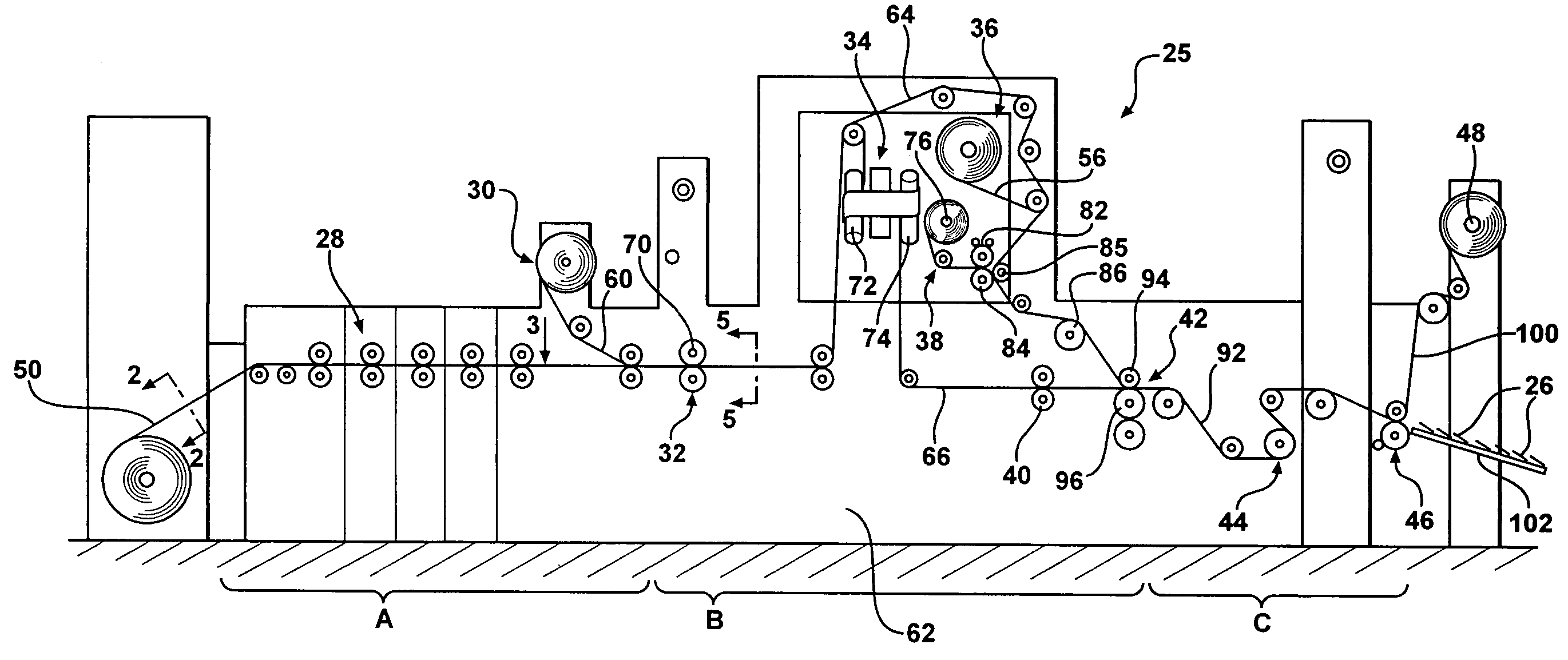
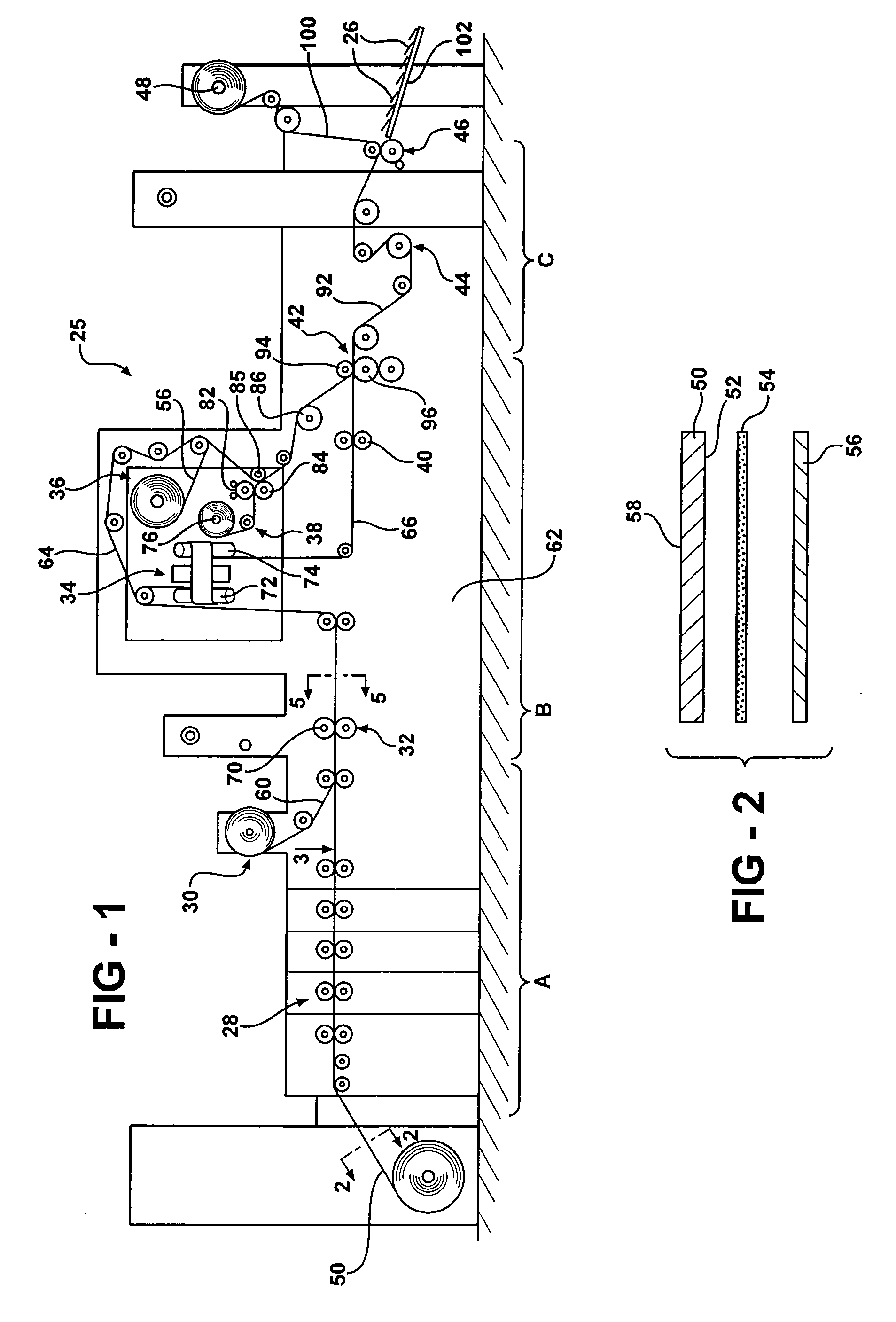
[0032] Referring to the Figures, wherein like numerals indicate like or corresponding parts throughout the several views, a manufacturing machine assembly 25 for producing an article 26 having a radio frequency identification (RFID) device 27 in accordance with the subject invention is generally shown in FIG. 1. The manufacturing machine assembly 25 is capable of producing any suitable article 26 or product, such as a promotional mailer, a hang tag assembly, a coupon card, a label of any type, a hanging card, or any other like device of any suitable size. The machine assembly 25 may be divided into three separate sections. Section A includes a printing station 28 and a laminating device 30. Section B includes a cutting device 32, an inverting device 34, a stripping device 36, an applicator 38, a scoring roller 40, and a pair of coupling rollers 42. Section C is an exit station and preferably includes a series of tensioning rollers 44, a pair of exit rollers 46, and a scrap take-up r...


PUM

PropertyMeasurementUnit
angleaaaaaaaaaa
angleaaaaaaaaaa
adhesiveaaaaaaaaaa

Abstract

A manufacturing machine assembly for producing an article having a radio frequency identification (RFID) device. The article is fabricated from a continuous sheet of stock with an adhesive layer and a release liner. A printing station prints indicia on the sheet of stock. A cutting station cuts the continuous sheet of stock to form first and second strips. The release liner is removed from the first strip to expose the adhesive layer and an applicator applies a number of the RFID devices to the exposed adhesive layer. Coupling rollers, each having an integral notch, bond the adhesive layer of the first strip with the second strip such that the RFID devices are sandwiched between the first and second strips. Alternatively, the release liner from the second strip may also be removed such that the adhesive layer of the first strip is bonded with the adhesive layer of the second strip to sandwich the RFID devices between the adhesive layers.

Description

CROSS-REFERENCE TO RELATED APPLICATIONS [0001] The subject patent application claims priority to and all the benefits of U.S. Provisional Patent Application Ser. No. 60 / 516,829, which was filed on Nov. 3, 2003.BACKGROUND OF THE INVENTION [0002] 1. Field of the Invention [0003] The subject invention relates to a manufacturing machine assembly for producing an article having a radio frequency identification (RFID) device. The subject invention also includes a method for producing such an article. [0004] 2. Description of Related Art [0005] Radio frequency identification (RFID) devices are well known in many industries and are utilized for a variety of purposes. In particular, RFID devices have been used in the past for security systems, tracking systems, data collection and management systems, valet communication systems, location systems and the like. The prior art has also contemplated the integration of these RFID devices into cards or multi-layered labels. U.S. Pat. No. 6,520,544 ...

Claims


Application Information

Patent Timeline
Patent Type & Authority Applications(United States)
IPC IPC(8): B21D39/03B23P11/00G06K19/077
CPCG06K19/07718G06K19/07749Y10T29/49829Y10T29/53526Y10T29/49831Y10T29/534
Inventor BEST, SCOTT D.TURNER, JAMES F.
Owner SAXON
Learn More