Printer and controlling method for printer

Inactive Publication Date: 2005-05-05
CANON KK
View PDF3 Cites 15 Cited by
  • Summary
  • Abstract
  • Description
  • Claims
  • Application Information

AI Technical Summary

Benefits of technology

[0013] The present invention is directed to a printer, and a method for controlling the printer, capable of reduced

Problems solved by technology

Therefore, printing takes a long time in comparison with other printers.
This makes the printing time much longer.
However, this printer requires increasing the size of the platen roller according to the size of the recording sheet.
In addition, in the case where a w

Method used


Image

  • Printer and controlling method for printer
  • Printer and controlling method for printer
  • Printer and controlling method for printer

Examples


Embodiment Construction

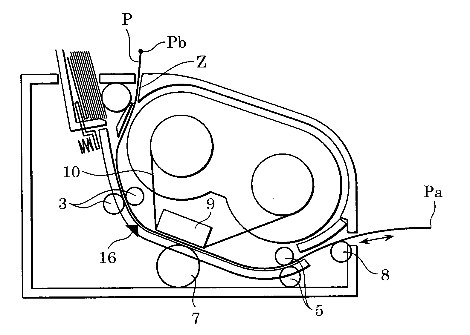
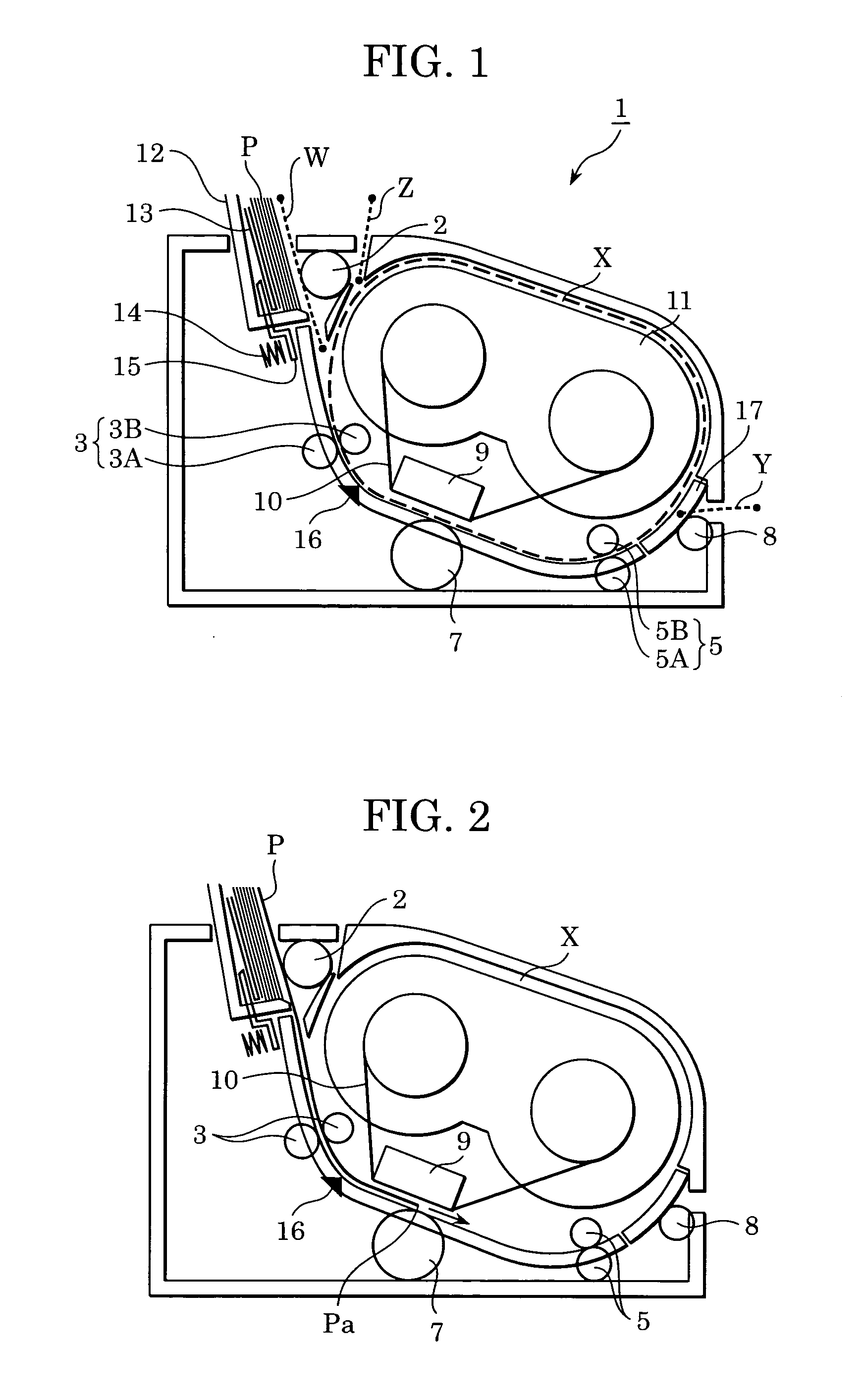
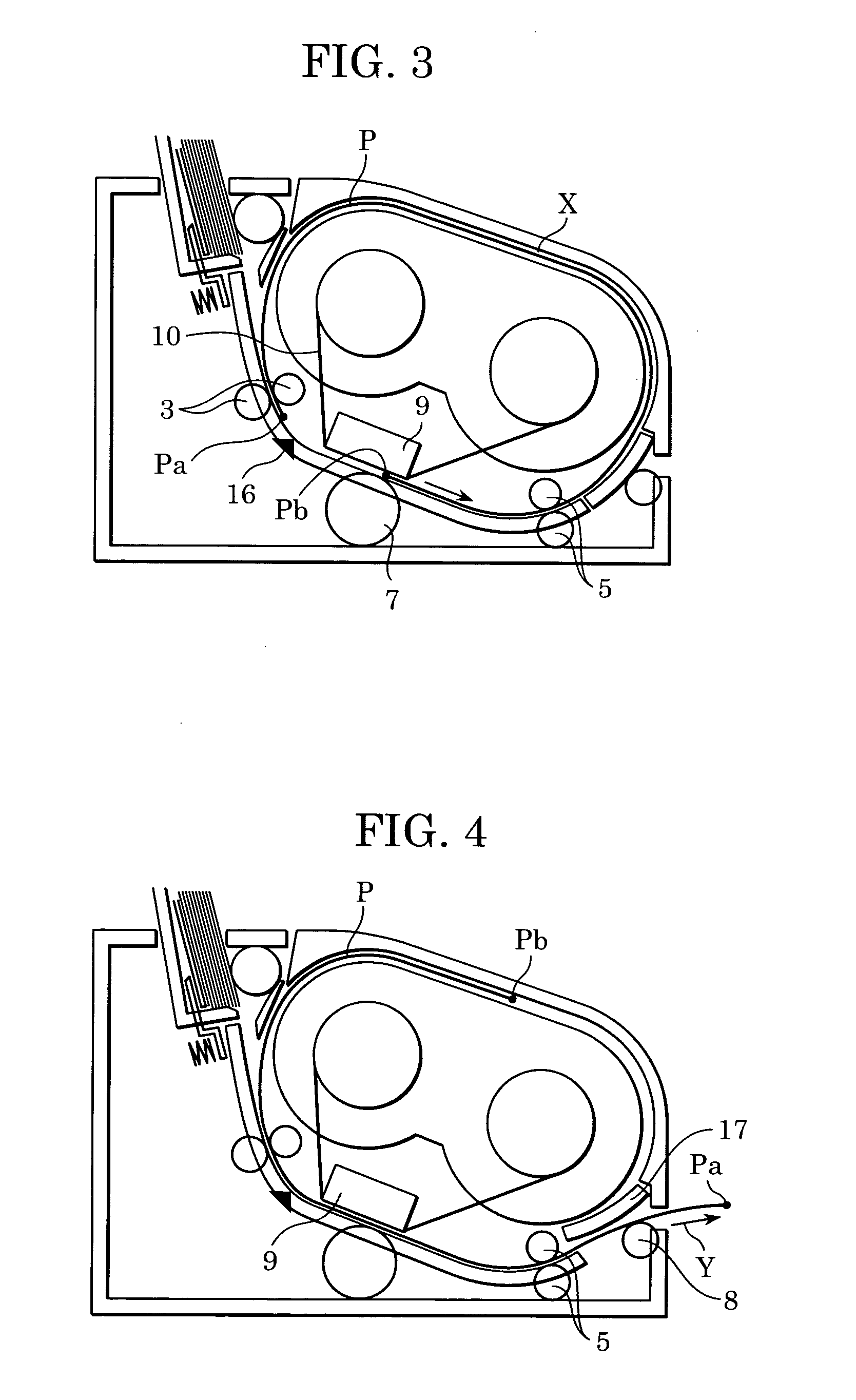
[0035] An embodiment of the present invention will now be described with reference to the drawings. FIG. 1 is a schematic vertical cross-sectional view showing the overall structure of a printer according to this embodiment.

[0036] Inside a printer body 1, an ink cassette 11 is accommodated in an accommodating portion. The ink cassette 11 contains an ink ribbon 10. Around the ink cassette 11, an oval circular path X is provided. At the ink-transferring portion, a thermal head 9 is provided inside the circular path X. Opposite the thermal head 9, a platen roller 7 is provided. Pressed between the platen roller 7 and the thermal head 9, the recording sheet P and the ink ribbon 10 come into contact with each other. The recording sheet P and the ink ribbon 10 are thus conveyed together. Heaters on the thermal head 9 are selectively heated, thus transferring ink applied to the ink ribbon 10 onto the recording sheet P. The ink cassette 11 can be inserted into or pulled out of the side wal...


PUM


Abstract

A printer and a method of controlling the printer. The printer includes a color ink ribbon and a thermal head for forming images on recording sheets and an accommodating portion accommodating the ink ribbon and the thermal head therein. The printer includes several paths for conveying the recording sheet including a circular path around the accommodating portion. Depending on the length of the recording sheet, the printer conveys the recording sheet along one of the several paths during a printing operation.

Description

CROSS REFERENCE TO RELATED APPLICATIONS [0001] This application claims priority from Japanese Patent Application No. 2003-370265 filed Oct. 30, 2003, which is hereby incorporated by reference herein. BACKGROUND OF THE INVENTION [0002] 1. Field of the Invention [0003] The present invention relates to a printer for forming an image on a recording medium such as a recording sheet based on image data, and also relates to a method for controlling the printer. [0004] 2. Description of the Related Art [0005] Printers are classified according to the method of image creation, such as thermal transfer printers, ink jet printers, laser printers, and wire dot printers. Thermal transfer printers perform dot line printing on a recording sheet with an ink ribbon. This type of printer has a plurality of heaters arranged in the main scanning direction. The heaters are selectively heated while the ink ribbon and the recording sheet are conveyed in the sub-scanning direction. Recently, with advances i...

Claims


Application Information

Patent Timeline
IPC IPC(8): B41J2/325B41J11/00B41J13/00B65H1/00B65H5/06B65H29/60B65H85/00
CPCB41J2/325B41J13/0054B41J13/0027B41J11/009
Inventor KITAMURA, GEN
Owner CANON KK
Why Eureka
Try Eureka