
Projection device and method for projecting image information onto a projection surface

a projection device and image information technology, applied in the field of projection devices, can solve the problems of too small projection surface and many applications, and achieve the effect of not restricting the size of the projected image information

Inactive Publication Date: 2020-10-22
ROBERT BOSCH GMBH
View PDF0 Cites 1 Cited by
  • Summary
  • Abstract
  • Description
  • Claims
  • Application Information

AI Technical Summary

Benefits of technology

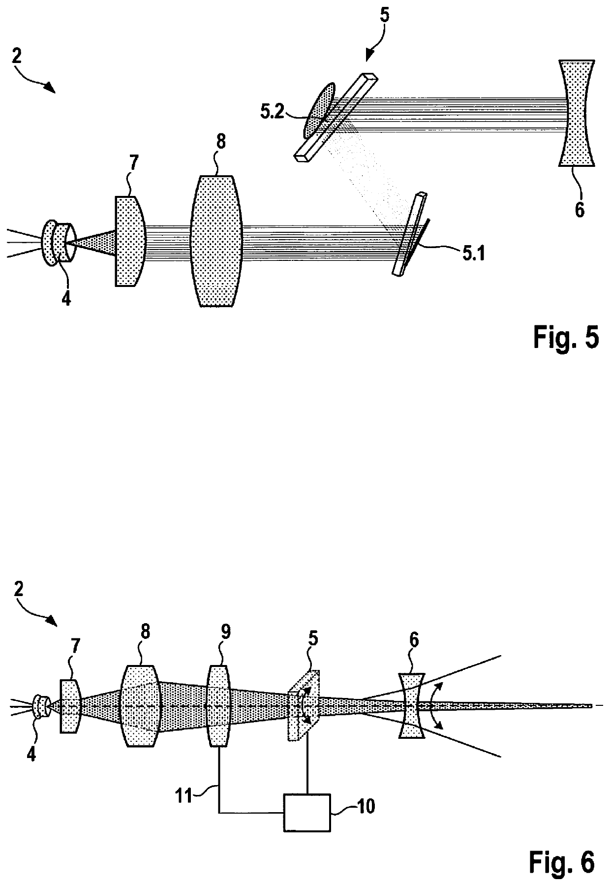
The present invention provides a projection device and a method for projecting image information onto a projection surface at a smaller projection distance without limiting the size of the projected image information. The device includes magnifying optics that increase the maximum achievable deflection of the laser beam, allowing for a sufficient large projection surface even with a small projection distance. A deflection element is included to change the direction of the laser beam, making it possible to project onto a inclined projection surface. The correction lens has an adjustable focal length to compensate for deformations of the projected image due to incorrect positioning of the optical elements. The correction lens includes a signal input connected to the control unit for controlling the micromirror unit, allowing for a dynamic correction of the projected image as a function of the deflection position of the micromirror unit.

Problems solved by technology

In this regard, the known projection devices have the disadvantage that due to the reduced projection distance, a projection surface results that is regarded as too small for many applications.

Method used


Image

  • Projection device and method for projecting image information onto a projection surface
  • Projection device and method for projecting image information onto a projection surface
  • Projection device and method for projecting image information onto a projection surface

Examples


Embodiment Construction

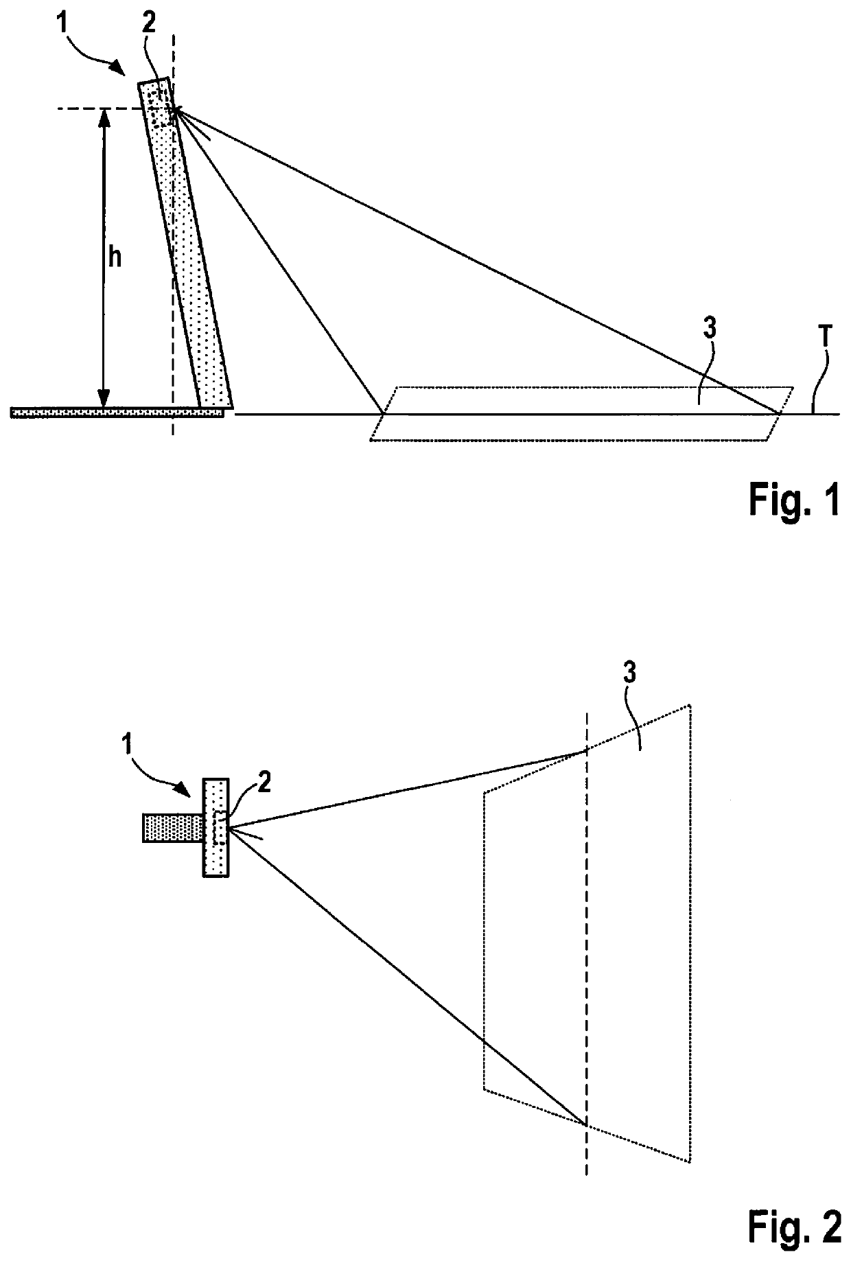
[0027]FIG. 1 illustrates a portable device 1 that may be configured as a smart phone, a camera, a PDA, or a tablet PC, for example. Portable device 1 includes a housing and a projection device 2, situated inside the housing, which is configured as a picoprojector. A control panel and / or a keyboard may be projected in the immediate vicinity of portable device 1 with the aid of projection device 2. The projection may take place on a tabletop T, for example, on which portable device 1 rests. The portable device is set on tabletop T in such a way that projection device 2 is situated at a distance h from the tabletop that is typically less than 0.5 m. Distance h may, for example, be 0.1 m to 0.3 m, which may be 0.1 m to 0.15 m.

[0028]FIG. 2 shows a top view onto the portable device. It is apparent that trapezoidal distortion of the image information projected onto projection surface 3 occurs.

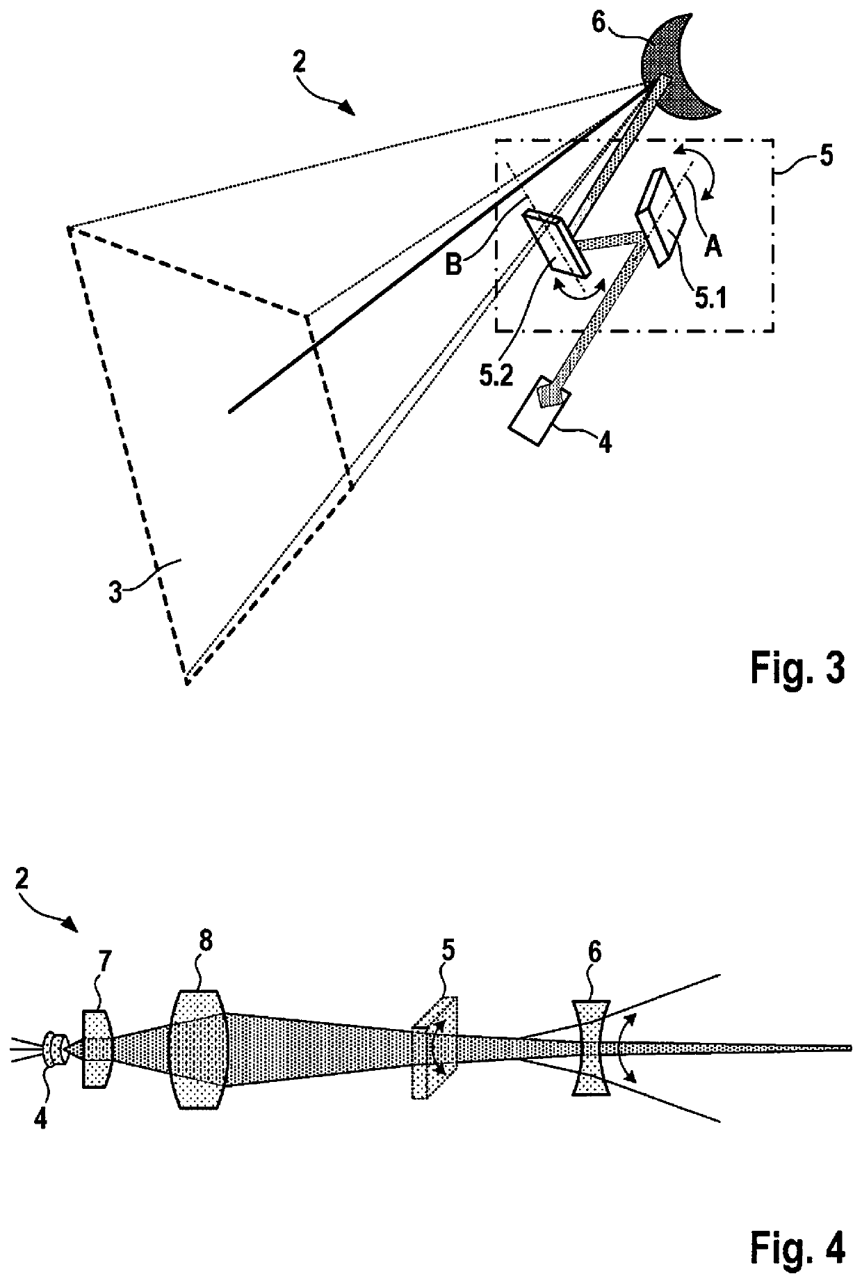
[0029]FIG. 3 illustrates a first exemplary embodiment of a projection device 2 according to the pr...


PUM


Abstract

A projection device for projecting image information onto a projection surface, including a laser for generating a laser beam, a micromirror unit for selectively deflecting the laser beam onto different image points of the projection surface, and magnifying optics, situated in the beam path of the laser beam, downstream from the micromirror unit, for increasing the deflection of the laser beam that is achievable via the micromirror unit. Also described is a method for projecting image information onto a projection surface, a laser beam being generated which is selectively deflected onto different image points of the projection surface via a micromirror unit, the deflection of the laser beam being increased via magnifying optics.

Description

FIELD OF THE INVENTION[0001]The present invention is directed to a projection device, and a related method.BACKGROUND INFORMATION[0002]Laser-based projection devices that include a micromirror unit for selectively deflecting the laser beam onto different image points of the projection surface play an increasingly important role in portable devices such as smart phones, cameras, PDAs, or tablet PCs. These types of image projectors are often based on raster scan methods in which the laser beam is imaged onto different image points of the projection surface, using adjustable micromirrors of the micromirror unit.[0003]Such projection devices have proven suitable in applications in which image information is projected onto a projection surface, for example a wall, which is relatively far away from the mobile device. In such applications, typical projection distances are in the range of 1 m and greater.[0004]In these types of portable devices there is a need for projecting image informati...

Claims


Application Information

Patent Timeline
Patent Type & Authority Applications(United States)
IPC IPC(8): H04N9/31G02B3/14G03B21/20G03B21/14G03B21/00
CPCG03B21/142G03B21/2033H04N9/3161G02B3/14G03B21/008H04N9/317G02B26/004G02B26/0833G02B26/101H04N9/3129H04N9/3152H04N3/08G02F1/29H04N9/3135H04N9/3173
Inventor PILARD, GAELFISCHER, FRANK
Owner ROBERT BOSCH GMBH
Learn More