Transient eutectic phase process for ceramic-metal bonding metallization and compositing

a technology of eutectic phase and ceramic metal, which is applied in the direction of welding/cutting media/materials, manufacturing tools, and solvents, etc., can solve the problems of not being able to withstand high temperatures or corrosion, not having all of the material properties, and unable to achieve the effect of less refractory

Inactive Publication Date: 2005-05-12
RUTGERS THE STATE UNIV
View PDF11 Cites 35 Cited by
  • Summary
  • Abstract
  • Description
  • Claims
  • Application Information

AI Technical Summary

Benefits of technology

[0005] A method is described herein for directly joining ceramics and metals. The method comprises forming a structure having a ceramic component, a metallic component and a metallic interlayer disposed between the ceramic component and the metallic component, the metallic interlayer being less refractory than the metallic component by means of a eutectic melt formed by adding a eutectic-forming reactant, such as a gas, an oxide of the metallic material of the interlayer or other compound, to the metallic interlayer (this is commonly termed gas-metal eutectic); and heating the structure to approximately a eutectic melting temperature of the eutectic-based interlayer system to form a metallic-material-based eutectic liquid that interacts with the metallic component to form a bond that directly joins the ceramic and metallic components to one another. The components may be bulk parts, metallization, ceramic coating layers, or compositing materials

Problems solved by technology

No single material is available today that possesses all of the material properties to meet the stringent demands of many traditional and advanced applications.
Metals, although ductile with high thermal and electrical conductivity, often cannot withstand high temperatures or corrosion, and expand significantly with increasing temperature.
Several joining technologies, which utilize interfacial methods, have proven effective for bonding ceramics and metals, but their high processing costs limit their penetration of some potential markets.

Method used


Image

  • Transient eutectic phase process for ceramic-metal bonding metallization and compositing
  • Transient eutectic phase process for ceramic-metal bonding metallization and compositing
  • Transient eutectic phase process for ceramic-metal bonding metallization and compositing

Examples


Embodiment Construction

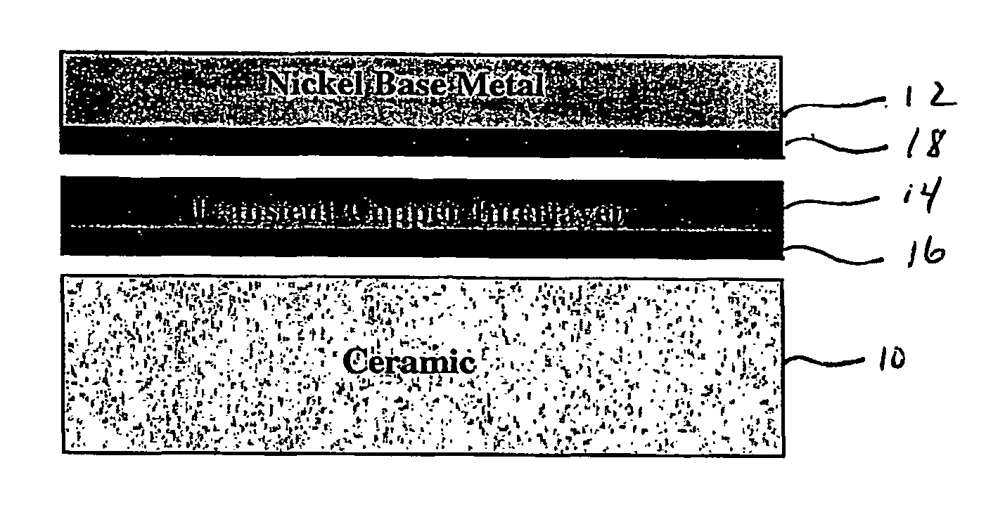
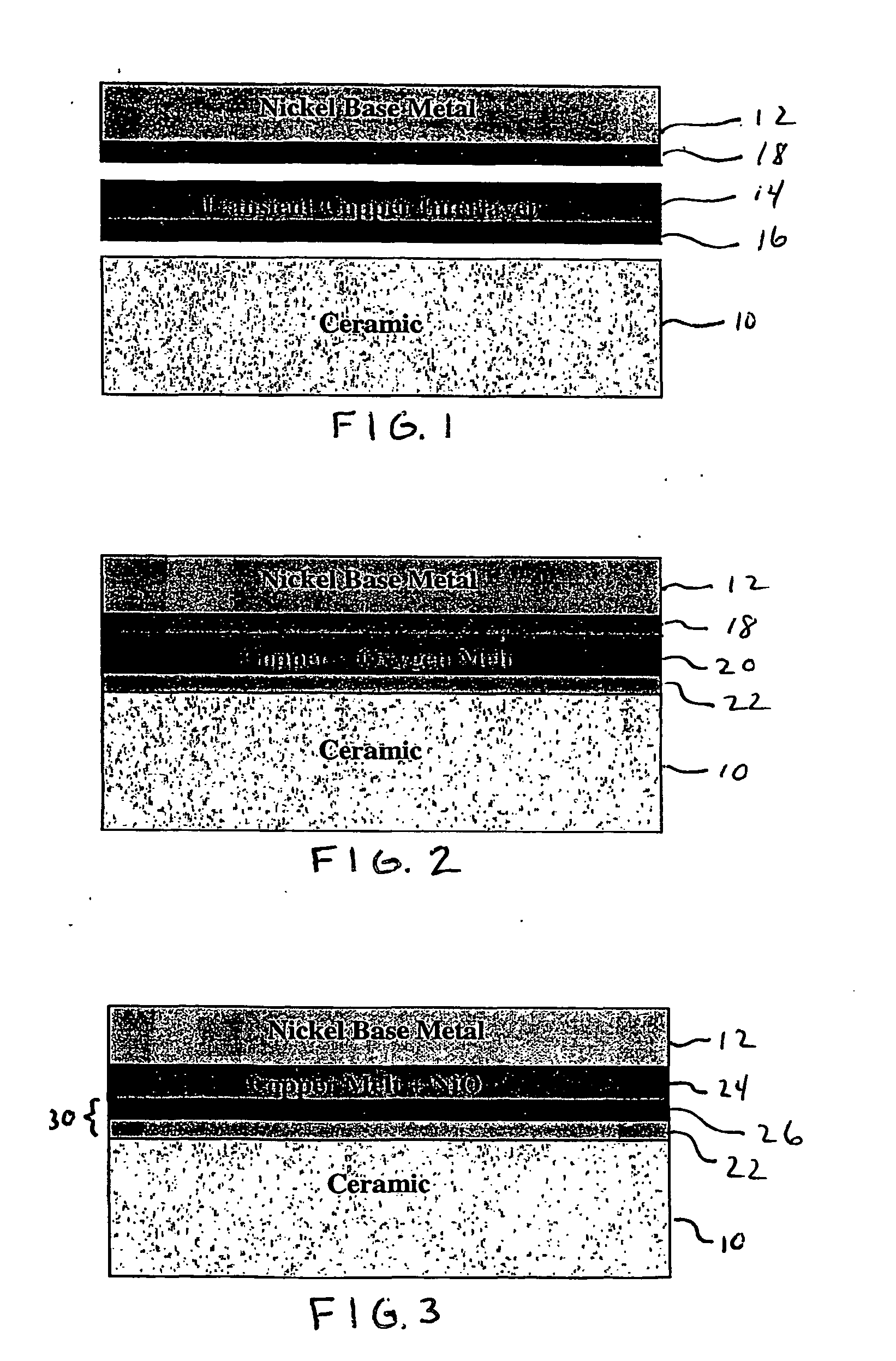
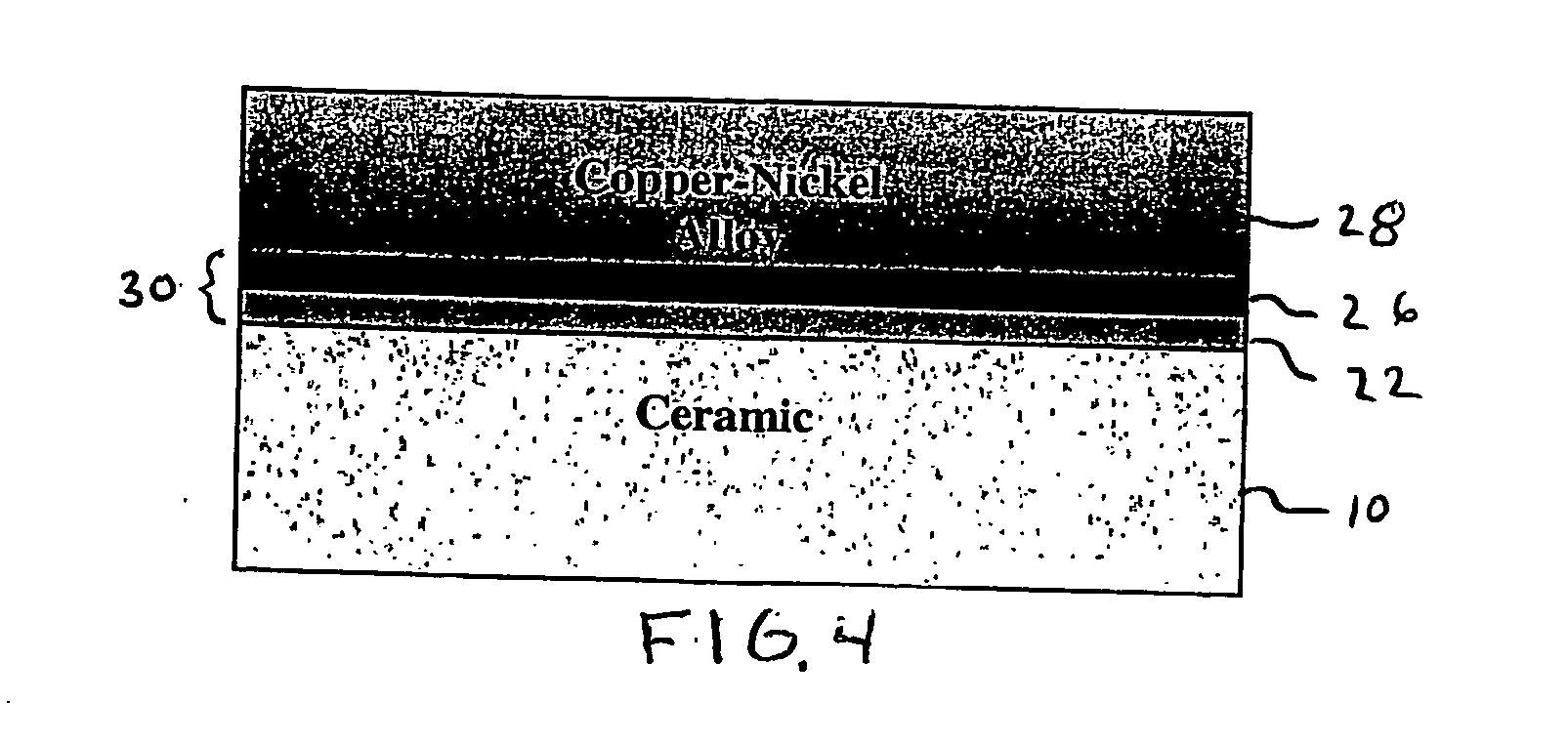
[0007] The present invention is a method of directly joining or bonding ceramics and metals (the terms “metal” and “metallic” being used herein to encompass metals, metal alloys, intermetallics, materials containing a substantial amount of metallically bonded materials, and any combination or combinations thereof) using a transient, low-temperature, metallic-material-based eutectic liquid or melt, i.e., where the metallic-material-based eutectic liquid “disappears” via solidification into a desired alloy or other metallically bonded material. To be consistent with current terminology and the illustrative embodiment to be described further on, the metallic-material-based eutectic liquid or melt will also be referred to hereinafter as “gas-metal eutectic.” It should be understood, however, that the eutectic constituents may also be provided by a liquid or solid in contact with an interlayer formed of a metallic material (metallic interlayer). The transient, low-temperature, metallic-m...


PUM

PropertyMeasurementUnit
eutectic melting temperatureaaaaaaaaaa
melting pointaaaaaaaaaa
melting temperatureaaaaaaaaaa

Abstract

A method for directly joining ceramics (10) and metals (12). The method involves forming a structure having a ceramic component (10), a more refractory metallic component and a less refractory metallic-material-based interlayer (14) disposed between the ceramic component (10) and the metallic component (12); adding a eutectic forming reactant to the metallic interlayer (14); and heating the structure to approximately a eutectic melting temperature of the reactant and the interlayer to form a metallic-material-based eutectic liquid that interacts with the metallic component to form a bond that directly joins the ceramic and metallic components to one another.

Description

FIELD OF THE INVENTION [0001] The present invention relates to ceramic-metal bonding, ceramic metallization and ceramic-metal compositing and more particularly, to a method that utilizes a low temperature transient metallic-material-based eutectic liquid to directly bond ceramic bulk materials and coatings to metals and visa versa, metallize ceramics and produce ceramic-metal composites in a wide variety of configurations. BACKGROUND OF THE INVENTION [0002] No single material is available today that possesses all of the material properties to meet the stringent demands of many traditional and advanced applications. Metals, although ductile with high thermal and electrical conductivity, often cannot withstand high temperatures or corrosion, and expand significantly with increasing temperature. An alternative to metals are ceramics, which are brittle insulators. Ceramics are refractory, hard, and wear-resistant, with excellent hot properties and relatively low thermal expansion. By jo...

Claims


Application Information

Patent Timeline
Patent Type & Authority Applications(United States)
IPC IPC(8): B23K35/00B23K35/30B23K35/38C04B35/10C04B37/02
CPCB23K35/001C04B2237/708B23K35/302B23K35/38B23K2203/18B32B2311/12B32B2311/22C04B35/01C04B35/10C04B37/023C04B37/025C04B37/026C04B2235/3279C04B2235/3281C04B2237/04C04B2237/124C04B2237/34C04B2237/343C04B2237/405C04B2237/407C04B2237/60B23K35/004B23K2103/18B23K2103/26B23K2103/52
Inventor GREENHUT, VICTOR ACHAPMAN, THOMAS R
Owner RUTGERS THE STATE UNIV
Why Eureka
Try Eureka