

Photographing optical lens assembly
a technology of optical lenses and lens assemblies, applied in the field of photographing optical lens assemblies, can solve the problems of inconvenient operation, inconvenient operation, and inability to meet the needs of the user, and achieve the effects of reducing the total track length of the lens assembly, reducing the sensitivity of the optical system, and improving the quality of the imag
- Summary
- Abstract
- Description
- Claims
- Application Information
AI Technical Summary
Benefits of technology
Problems solved by technology
Method used
Image

Examples
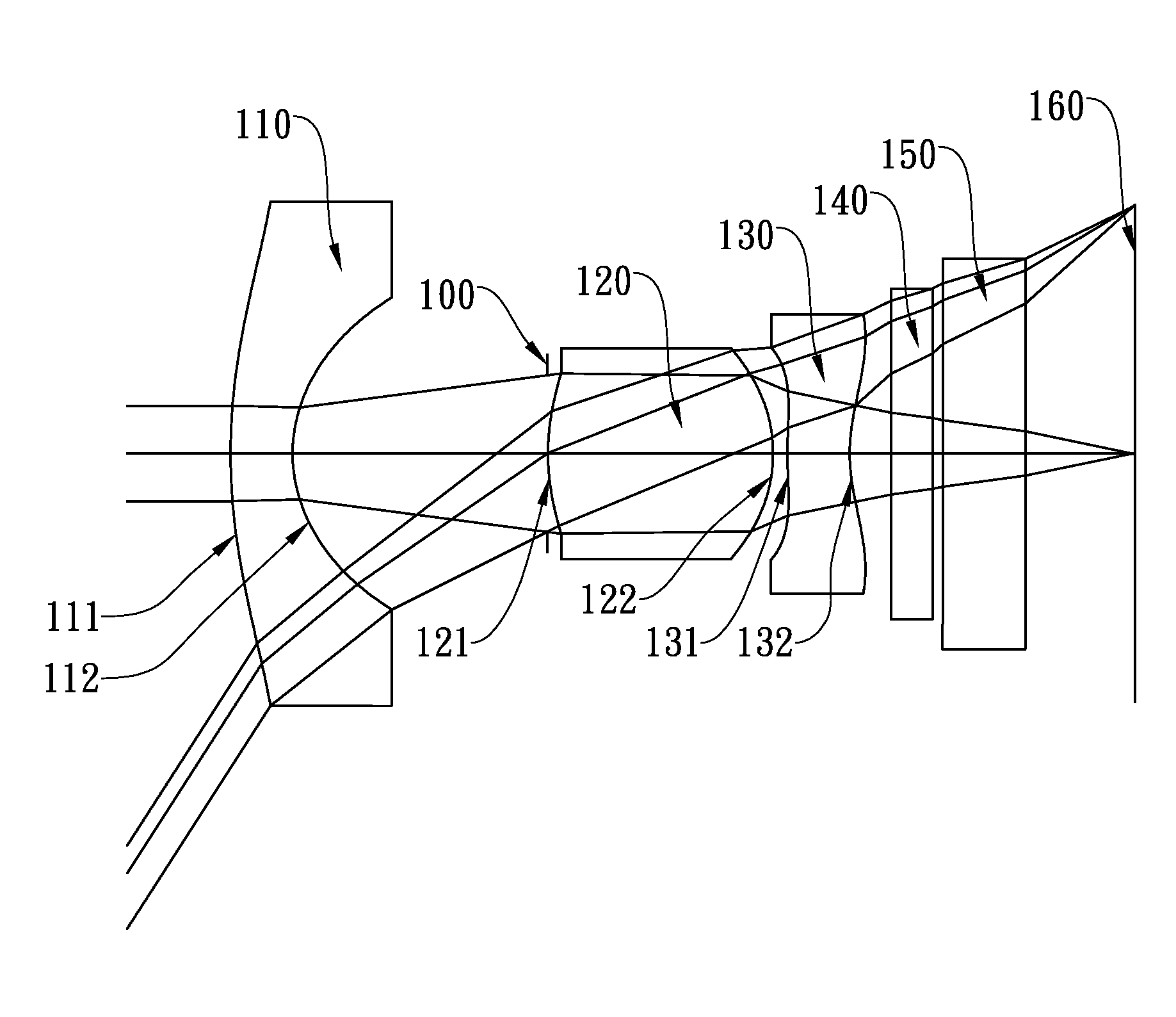
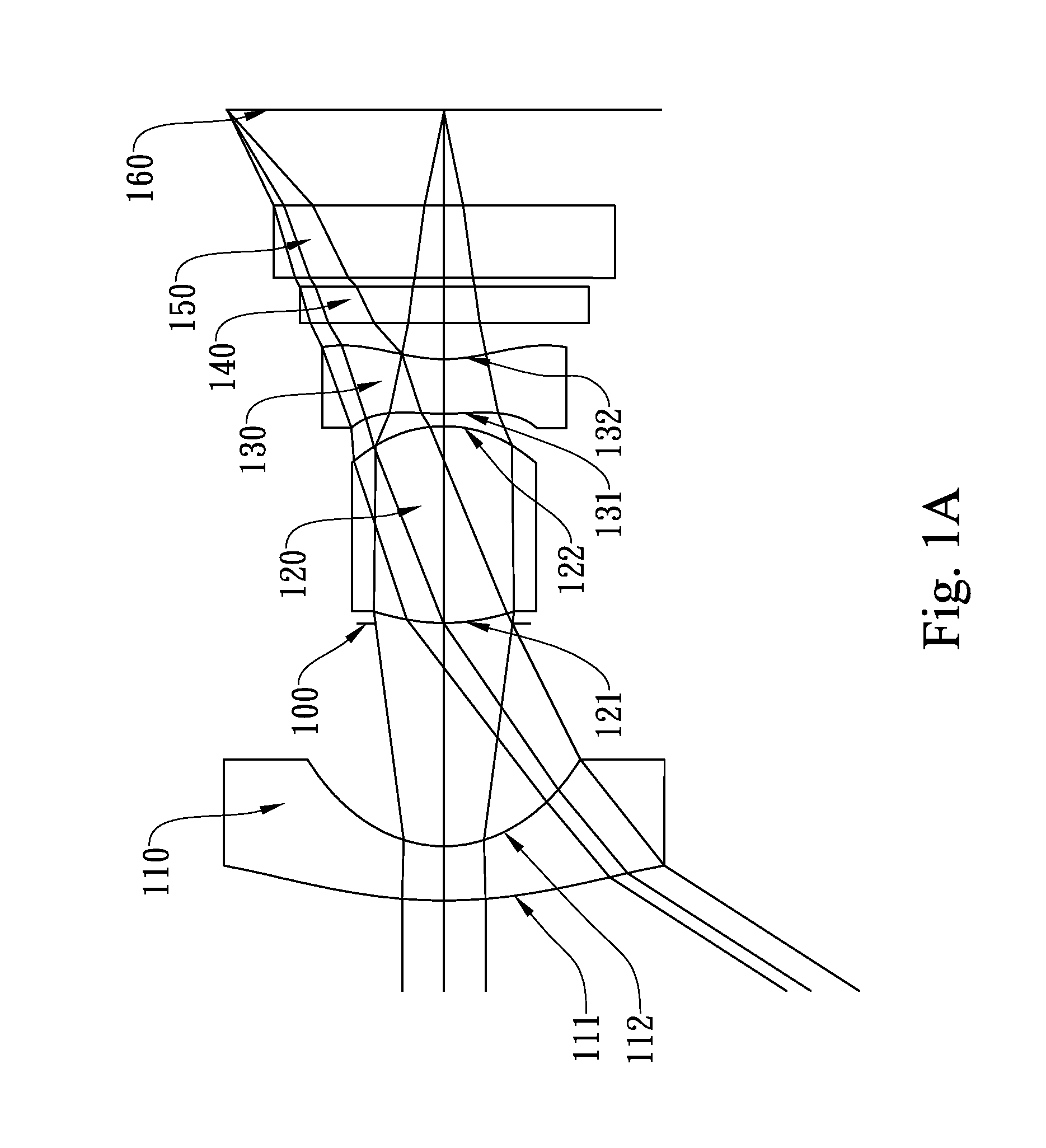
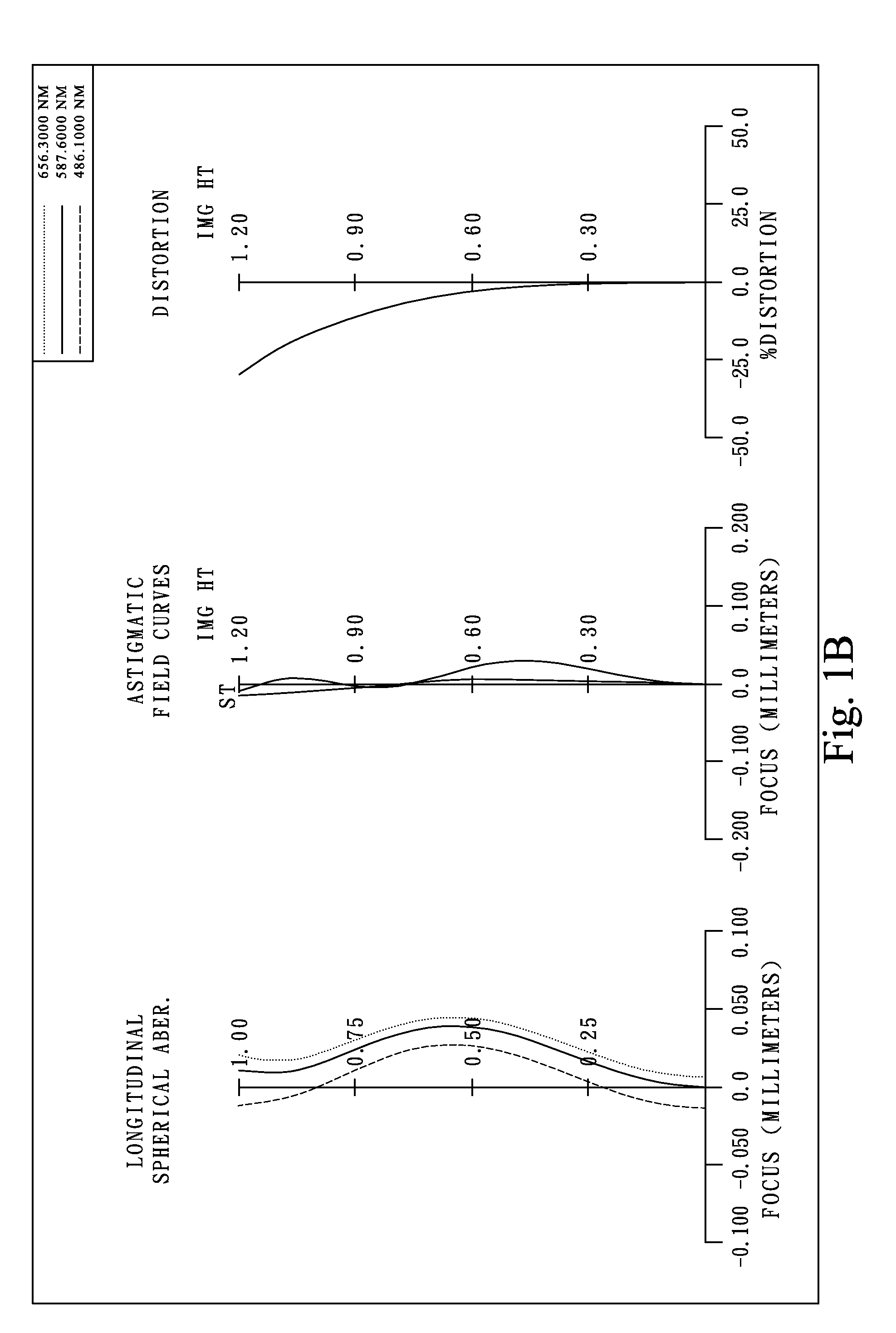
first embodiment
[0059]In the present photographing optical lens assembly, the focal length of the photographing optical lens assembly is f, and it satisfies the relation: f=1.14 (mm).
[0060]In the first embodiment of the present photographing optical lens assembly, the f-number of the photographing optical lens assembly is Fno, and it satisfies the relation: Fno=2.43.
[0061]In the first embodiment of the present photographing optical lens assembly, half of the maximal field of view of the photographing optical lens assembly is HFOV, and it satisfies the relation: HFOV=57.2 deg.
[0062]In the first embodiment of the present photographing optical lens assembly, the Abbe number of the second lens element 120 is V2, the Abbe number of the third lens element 130 is V3, and they satisfy the relation: V2−V3=32.5.
[0063]In the first embodiment of the present photographing optical lens assembly, the focal length of the photographing optical lens assembly is f, the distance on the optical axis between the first l...
second embodiment
[0073]In the present photographing optical lens assembly, the focal length of the photographing optical lens assembly is f, and it satisfies the relation: f=1.11 (mm).
[0074]In the second embodiment of the present photographing optical lens assembly, the f-number of the photographing optical lens assembly is Fno, and it satisfies the relation: Fno=2.43.
[0075]In the second embodiment of the present photographing optical lens assembly, half of the maximal field of view of the photographing optical lens assembly is HFOV, and it satisfies the relation: HFOV=58.0 deg.
[0076]In the second embodiment of the present photographing optical lens assembly, the Abbe number of the second lens element 220 is V2, the Abbe number of the third lens element 230 is V3, and they satisfy the relation: V2−V3=32.5.
[0077]In the second embodiment of the present photographing optical lens assembly, the focal length of the photographing optical lens assembly is f, the distance on the optical axis between the fir...
third embodiment
[0087]In the present photographing optical lens assembly, the focal length of the photographing optical lens assembly is f, and it satisfies the relation: f=1.00 (mm).
[0088]In the third embodiment of the present photographing optical lens assembly, the f-number of the photographing optical lens assembly is Fno, and it satisfies the relation: Fno=2.80.
[0089]In the third embodiment of the present photographing optical lens assembly, half of the maximal field of view of the photographing optical lens assembly is HFOV, and it satisfies the relation: HFOV=58.0 deg.
[0090]In the third embodiment of the present photographing optical lens assembly, the Abbe number of the second lens element 320 is V2, the Abbe number of the third lens element 330 is V3, and they satisfy the relation: V2−V3=32.5.
[0091]In the third embodiment of the present photographing optical lens assembly, the focal length of the photographing optical lens assembly is f, the distance on the optical axis between the first l...
PUM
 Abstract
Description
Claims
Application Information