Tube inverting device and method for using same

a technology of inverting device and tube, which is applied in the direction of dough shaping, hollow wall objects, manufacturing tools, etc., can solve the problems of resin being squeezed from the liner, large, bulky, and weighing several hundred pounds, and the operator cannot adjust the bladder fluid pressur

Inactive Publication Date: 2005-05-12
BLUE SKY FOREVER
View PDF5 Cites 19 Cited by
  • Summary
  • Abstract
  • Description
  • Claims
  • Application Information

AI Technical Summary

Benefits of technology

[0039] The present invention allows installations to be simple and the installation operator to be hands free during the inversion of a liner. It is self-adjusting, self-regulating, and does not apply any more pressure on to the liner than is minimally required for the liner to invert forward into a pipe line.

Problems solved by technology

One disadvantage of presently existing pressure vessel 5 is that they are large, bulky, and weigh several hundred pounds.
The operator cannot adjust the bladder fluid pressure in a quick fashion which again often results in resin being squeezed from the liner.
Resin being squeezed out is unacceptable.
One disadvantage of the device 32 shown in FIG. 6 is that the head 38 must be changed for different sized tubes 26.
This means that one cannot quickly make the opening smaller or tighter around the liner tube.

Method used


Image

  • Tube inverting device and method for using same
  • Tube inverting device and method for using same
  • Tube inverting device and method for using same

Examples


Embodiment Construction

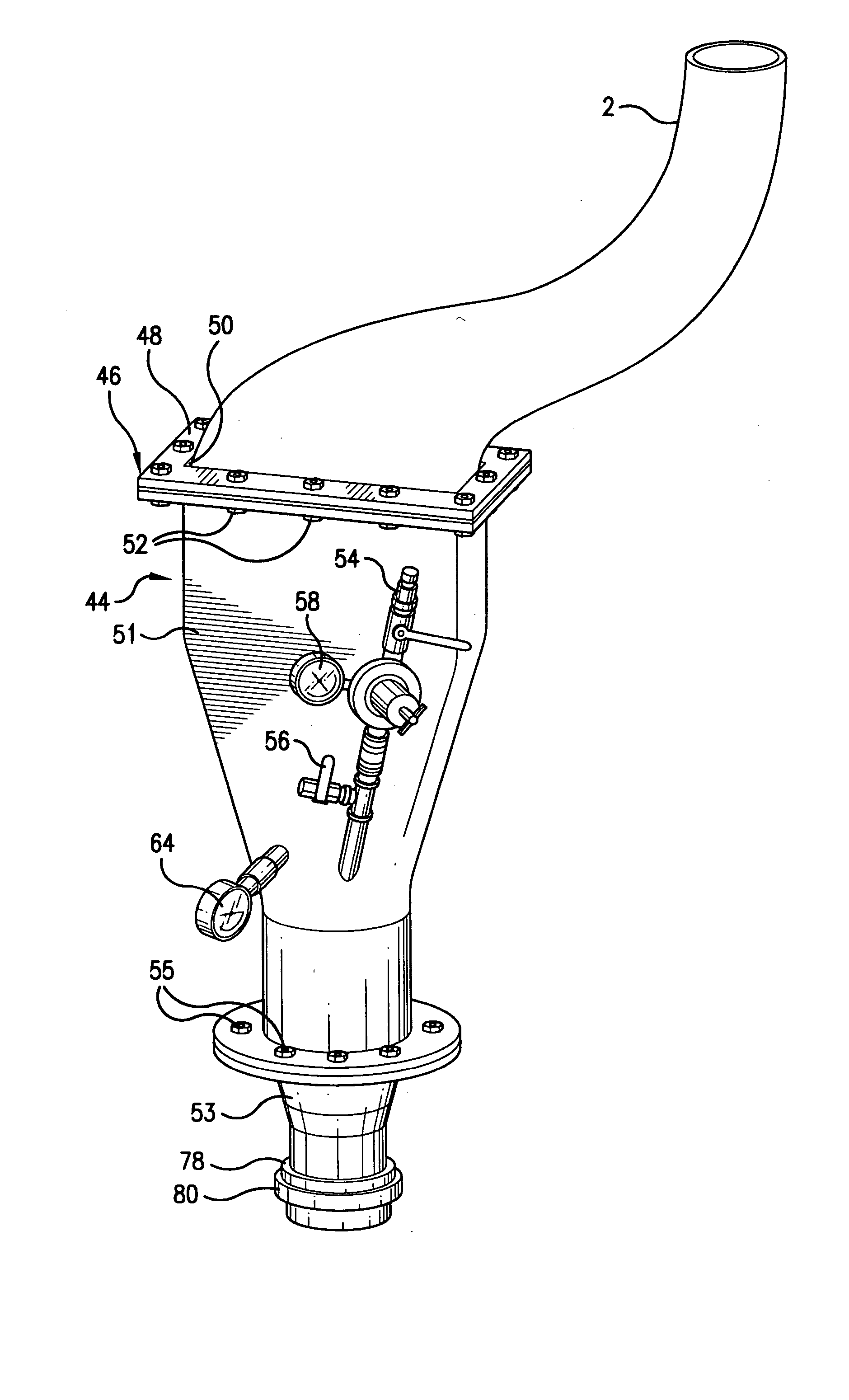
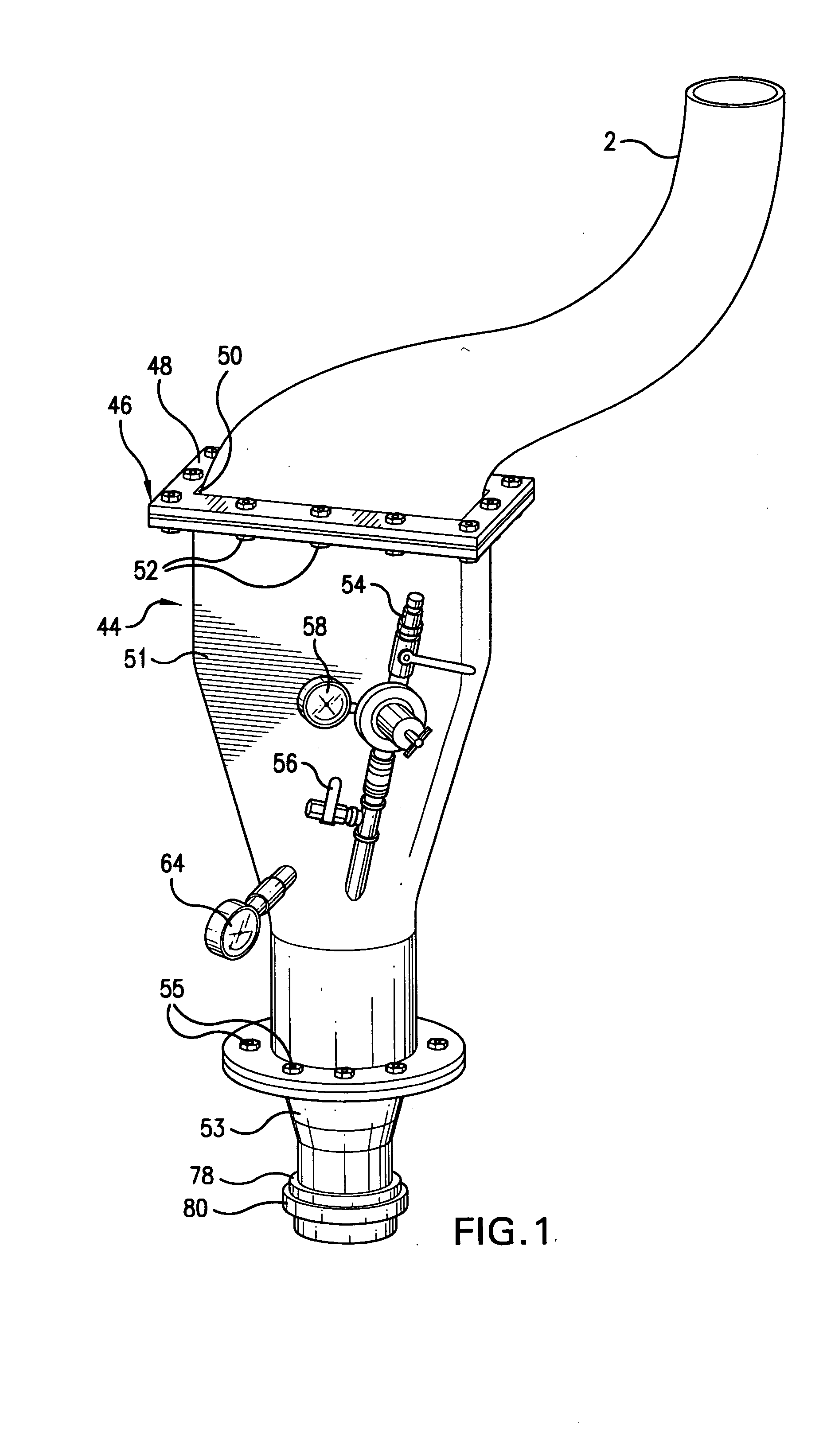
[0047] Referring to FIGS. 1-4, the inverting device is generally designated by the numeral 44. Device 44 includes a housing 46 having a removable cap 48 bolted thereon by bolts 52. The cap 48 includes an inlet opening 50 which can be of varying shapes and sizes, but is preferably a rectangular shape sufficient large to receive liner tubes of varying sizes and dimensions.

[0048] Housing 46 includes a middle housing section 51 which is bolted at its upper end to cap 48 and which is bolted at its lower end to a bottom housing section 53 by bolts 55.

[0049] Within the housing 46 is an inverting chamber 62. A pressure inlet hose 54 includes a shutoff valve 56 and a pressure gauge 58. The pressure inlet hose 54 is in communication with the interior of the inverting chamber 62 through a pressure inlet opening 60.

[0050] A chamber pressure gauge 64 is also in communication with the inverting chamber 62 through a gauge opening 66 so as to register the fluid pressure within the inverting cham...


PUM

PropertyMeasurementUnit
perimeteraaaaaaaaaa
flexibleaaaaaaaaaa
shapeaaaaaaaaaa

Abstract

The tube inverting device of the present invention includes a housing having an inlet opening at one end and an outlet opening at the other end. A liner tube is attached to the outlet opening and extends through the chamber and out of the chamber through the inlet opening. The bladder tube is attached adjacent the inlet opening, and includes a free end extending within the chamber and surrounding the liner tube. Fluid pressure is introduced into the chamber outside the liner tube and the bladder tube and forces the inversion of the liner tube from the outlet opening of the housing while at the same time causing the bladder tube to squeeze against and seal the outer surface of the liner tube.

Description

BACKGROUND OF THE INVENTION [0001] This invention relates to a tube inverting device and method for using same. [0002] Various methods have been used for delivering a repair liner to a place within a pipe that has been damaged. [0003] One method includes the use of a pressure vessel that houses the liner tube. The vessel is pressurized so as to cause the liner to invert forwardly out of the vessel into the pipe to be repaired. During this inversion process the liner tube is reversed in the same fashion as a sock that is reversed upon itself as it is removed. [0004] One disadvantage of presently existing pressure vessel 5 is that they are large, bulky, and weigh several hundred pounds. The size and weight of the pressure vessel dictates whether or not a repair can be made. [0005] Efforts have been made to reduce the size of the vessel for carrying the liner tube. One of these examples is a chip unit which is shown in FIG. 5 of the drawings. The chip unit is identified by the numeral ...

Claims


Application Information

Patent Timeline
Patent Type & Authority Applications(United States)
IPC IPC(8): B29C63/36F16L55/18
CPCB29C63/36F16L55/18F16L55/1651
Inventor KIEST, LARRY W. JR.
Owner BLUE SKY FOREVER
Why Eureka
Try Eureka