Method and system for fault isolation within a network element in an optical network

a fault isolation and optical network technology, applied in the field of optical communication networks, can solve the problems of system alarms, network elements in optical networks are subject, and system alarms can be raised, and the system can however give rise to multiple alarms detected

Inactive Publication Date: 2005-05-12
ALCATEL LUCENT CANADA
View PDF3 Cites 35 Cited by
  • Summary
  • Abstract
  • Description
  • Claims
  • Application Information

AI Technical Summary

Benefits of technology

[0010] A system for fault isolation within a network element (NE) in an optical network, wherein the NE has a view of a network topology and Wavelength Tracker data obtained by using Wavelength Tracker technology, the optical network contains optical channel paths, each having a unique signature in a form of a low frequency dither tone modulation called Wavekey, generated by Wavelength Tracker, the system comprising: means for identifying root cause alarms in the NE; and a display unit for displaying said root cause alarms. The means for identifying the root cause alarms in the NE comprises a means for masking non-root cause alarms in the NE.

Problems solved by technology

A network element in an optical network is subject to intermittent faults that may raise alarms in the system.
A single fault in the system can however give rise to multiple alarms detected at multiple points.
With a large number of alarms in the list, this can be a long and arduous task.
It cannot only overwhelm even an experienced network operator but can also increase the time for the detection of the failure.
This in turn can significantly increase the time required for returning service to the network element.

Method used


Image

  • Method and system for fault isolation within a network element in an optical network
  • Method and system for fault isolation within a network element in an optical network
  • Method and system for fault isolation within a network element in an optical network

Examples


Embodiment Construction

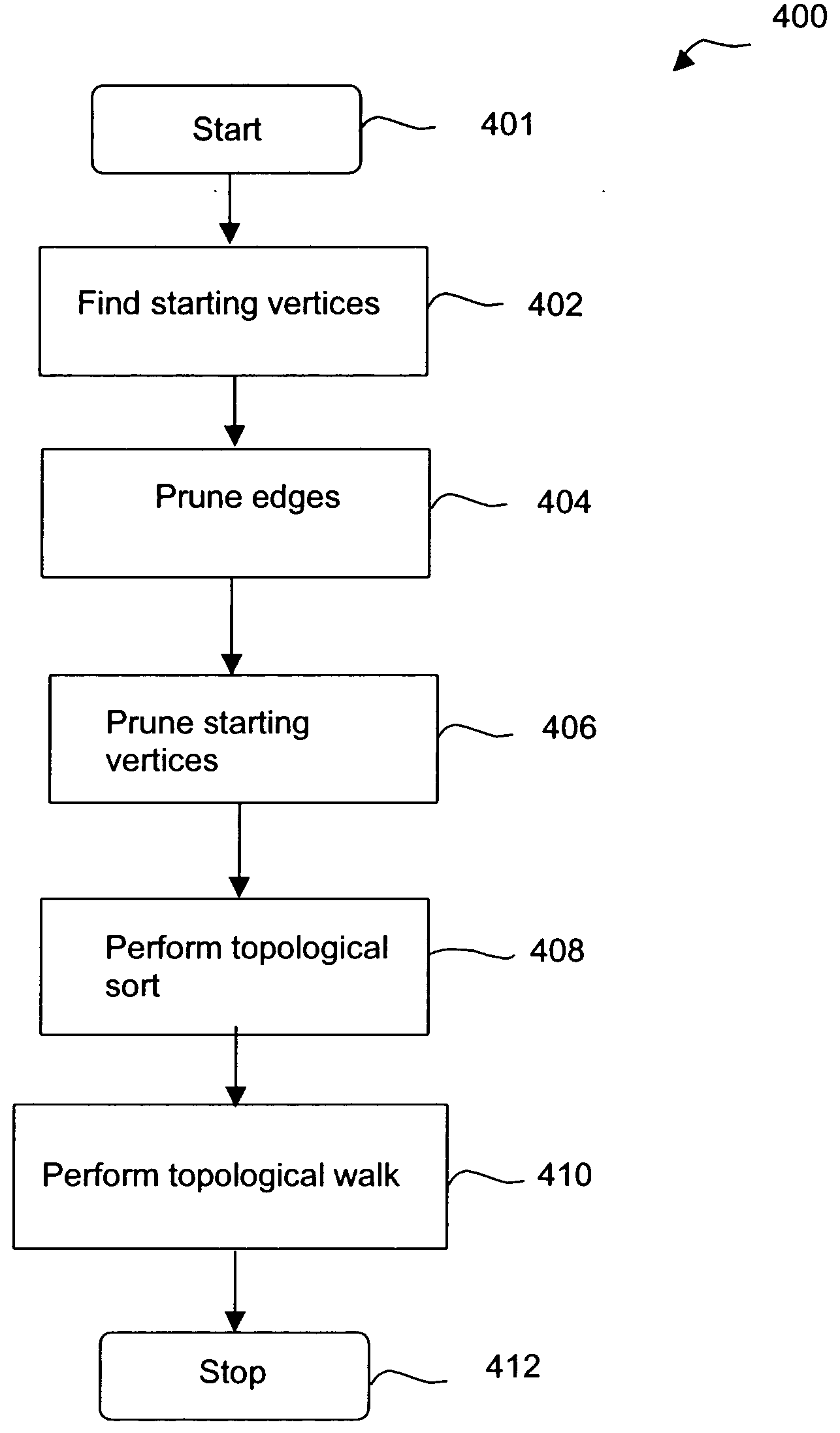
[0019] Multiple alarms may appear against many cards in the NE when a fault occurs. The focus here is on alarms that will appear against many cards in the NE when the fault occurs. This invention reduces the number of alarms presented to the user to a minimum set in order to help diagnose the problems. The root cause alarms that correspond to the root cause fault conditions in the system are displayed and all correlated non-root cause alarms within any network element in the optical network are masked.

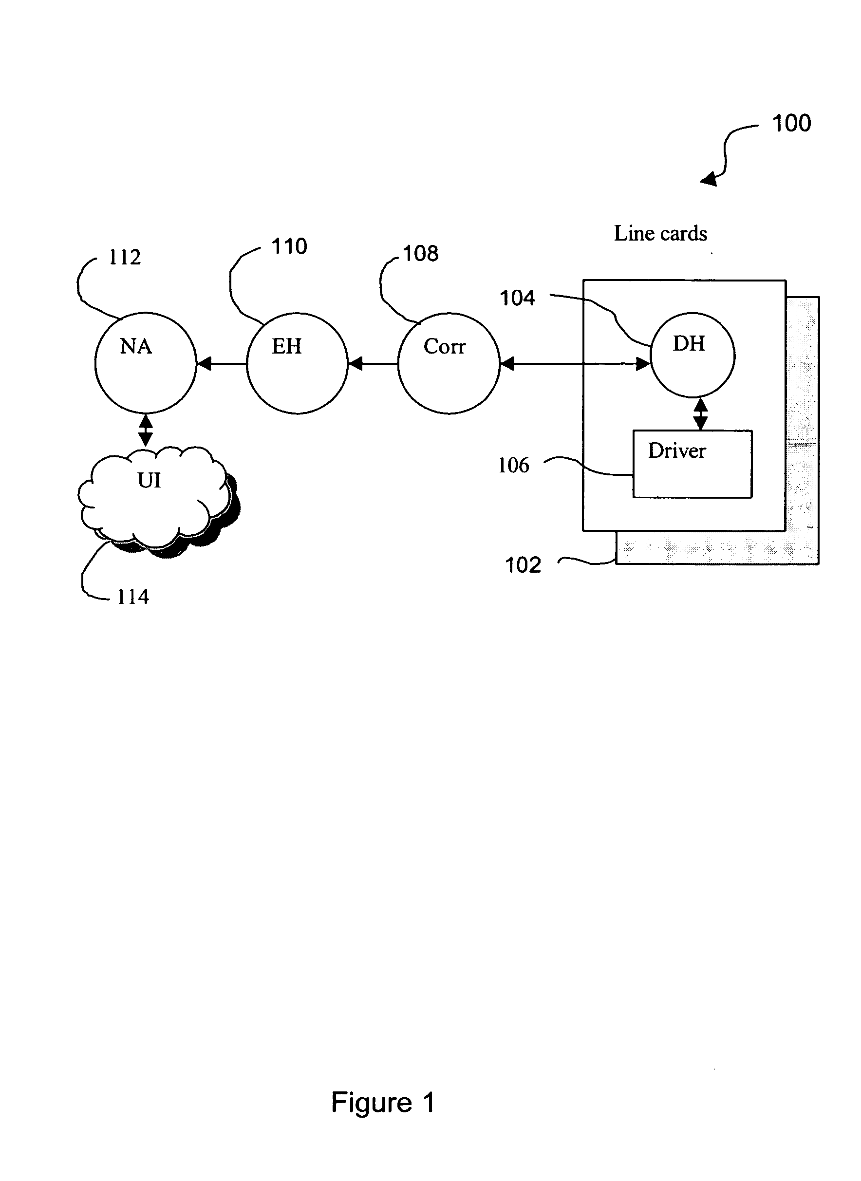
[0020] Tropic Network's Wavelength Tracker technology is useful in monitoring of optical networks that contains optical channel paths. Monitoring of faults that give rise to alarms in the optical channel layer is achieved by deploying Wavelength Tracker. A light path to be monitored on an optical network can be identified by using Wavelength Tracker. The Wavelength Tracker technology applies a unique optical signature to each wavelength (channel) at the Dense Wavelength Division Multi...


PUM


Abstract

A method and system for fault isolation within a network element in an optical network is described. A single fault in the system can give rise to multiple alarms detected at multiple points. Finding the root cause alarm corresponding to the fault that has triggered these alarms is important for fault isolation and is the focus of attention for this invention. The network element is modeled by a directed acyclic graph that captures the interactions among various components in the network element. Using a graph-based technique the invention analyzes the various topological faults raised and their locations for identifying root cause alarms and masking all correlated alarms.

Description

[0001] This application claims priority from U.S. Provisional Patent Application Ser. No. 60 / 518,629 to CASTONGUAY et al., entitled “Method and apparatus for suppression of alarms across network elements”, and filed on 12 Nov. 2003.FIELD OF INVENTION [0002] The invention relates to optical communication networks, and in particular to a method and system for determining the root cause alarm and masking all other non-root cause alarms e.g. for the purpose of fault isolation within a single network element of the network. BACKGROUND OF INVENTION [0003] A network element in an optical network is subject to intermittent faults that may raise alarms in the system. A single fault in the system can however give rise to multiple alarms detected at multiple points. Finding the root cause alarm corresponding to the fault that has triggered these alarms is important for fault isolation and repair. [0004] In the absence of an automatic fault isolation system, the network operator has to manually...

Claims


Application Information

Patent Timeline
Patent Type & Authority Applications(United States)
IPC IPC(8): G06T17/00H04B10/08H04L12/24
CPCH04L41/0659H04L41/0631
Inventor CASTONGUAY, ARTHUR EMERYGROVES, JOHN FREDERICK
Owner ALCATEL LUCENT CANADA
Why Eureka
Try Eureka