Image capturing apparatus and camera module

a technology camera module, which is applied in the field of image capturing apparatus, can solve the problems that users have to perform various cumbersome operations, and achieve the effect of quick switching a scene photographing mode and simple manner

Inactive Publication Date: 2005-05-12
CASIO COMPUTER CO LTD
View PDF5 Cites 40 Cited by
  • Summary
  • Abstract
  • Description
  • Claims
  • Application Information

AI Technical Summary

Benefits of technology

[0007] The present invention has been made to solve the above-explained problems, and therefore, has an object to provide an image capturing apparatus such as a folding type portable electron

Problems solved by technology

However, in the above-described constructions of these conventional portable telephones equipped with cameras, when these conventional portable telephones are us

Method used


Image

  • Image capturing apparatus and camera module
  • Image capturing apparatus and camera module
  • Image capturing apparatus and camera module

Examples


first embodiment

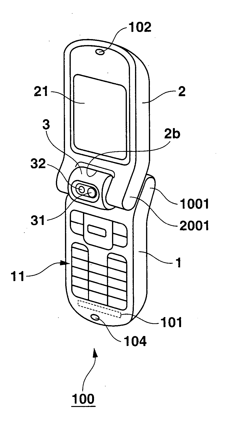
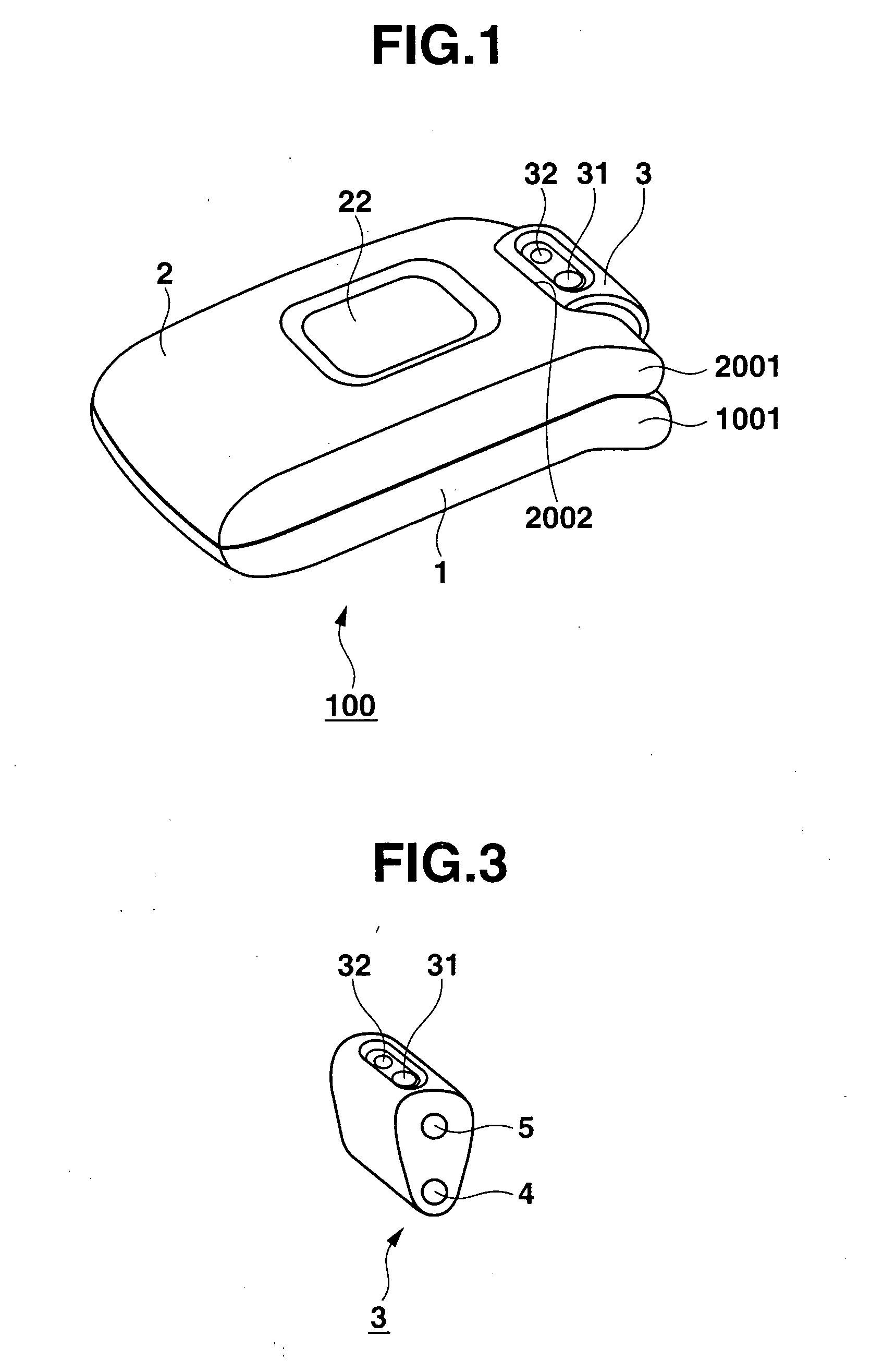
[0073] As previously explained, in the portable telephone 100 of the first embodiment mode, the coupling portion 3 is coupled to the main body portion 1 in the pivotable manner by the first hinge portion 4, and also, is coupled to the lid portion 2 in the pivotable manner by the second hinge portion 5.

[0074] Under such a condition that the lid portion 2 is overlapped on the main body portion 1, as shown in FIG. 1 and FIG. 4A, in the portable telephone 100, the camera portion 31 mounted on the coupling portion 3 is directed from the side of the main body portion 1 to the side of the lid portion 3.

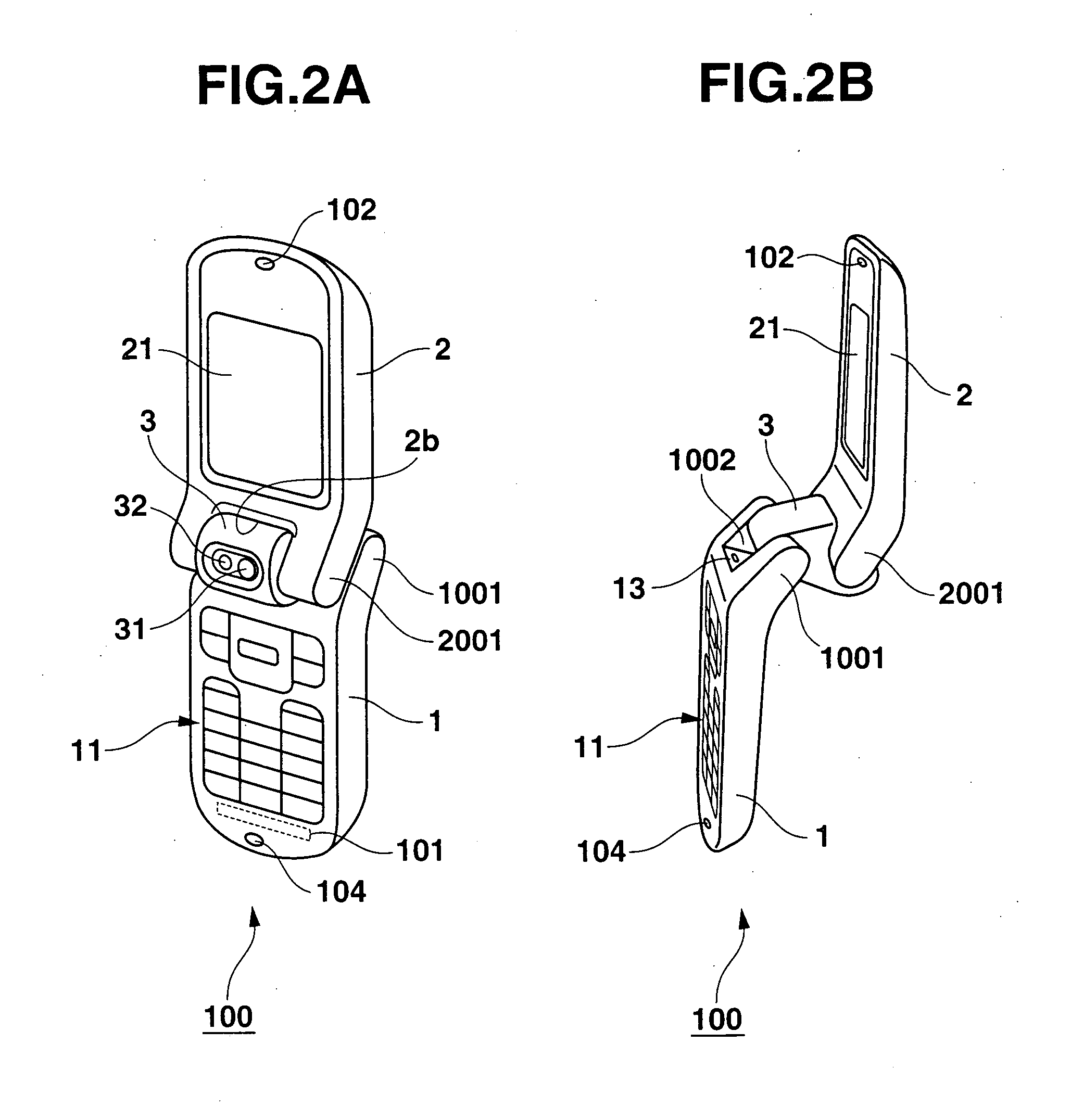
[0075] Then, the lid portion 2 is moved by the second hinge portion 5 of the coupling portion 3 in the pivotable manner so as to be opened with respect to the main body portion 1 from such a condition that this lid portion 2 is overlapped on the main body portion 1. Thus, when such a condition is obtained under which, as represented in FIG. 2A and FIG. 4B, the bent edge portion 1001 of the ...

embodiment 2

[0080] A portable telephone 200 according to an embodiment mode 2 of the present invention will now be described with reference to FIG. 6 through FIG. 9D. It should be noted that the same reference numerals shown in the basic structure of the portable telephone 100 according to the embodiment mode 1 will be employed as those for denoting the same, or similar structural members of the portable telephone 200 and explanations thereof are omitted. As shown in these drawings, a coupling portion 3 owns a bent extension portion 3001. This bent extension portion 3001 is bent from a second hinge portion 5 on the side of a lid portion 2 and is extended. Both a camera portion 31 and a flash-purpose LED (light emitting member) 32 are arranged on a tip plane of the bent extension portion 3001.

[0081] Then, a notch portion 2003 is formed in the lid portion 2. While a dimension of this notch portion 2003 is made larger than the dimension of the above-described notch portion 2002 of the embodiment ...

embodiment 3

[0094] An electric connection and an imaging operation of a portable telephone 400 according to an embodiment mode 3 will now be described in detail, to which the present invention has been applied. It should be understood that an outer view of the portable telephone 400 is similar to that of the above-described embodiment mode 1, or embodiment mode 2. It should also be noted that the same reference numerals shown in the basic structure of the portable telephones 100 and 200 according to the embodiment modes 1 and 2 will be employed as those for denoting the same, or similar structural members of the portable telephone 400 and explanations thereof are omitted.

[0095]FIG. 10 is a diagram for illustratively showing an electric connection structure of electronic components provided in a space formed by coupling the main body portion 1 via the coupling portion 3 to the lid portion 2.

[0096] As indicated in FIG. 10, a main body portion board 14 is mounted inside the main body portion 1. ...


PUM


Abstract

In a folding type portable electronic appliance, the portable electronic appliance is equipped with a main body portion having a wireless unit, a lid portion having a display unit, and a coupling portion for hinge-coupling the main body portion in a pivotable manner on one edge side thereof and for hinge-coupling the lid portion in a pivotable manner on the other edge side thereof. In the portable electronic appliance, the lid portion is foldable with respect to the main body portion, and a camera module is further provided on the coupling portion, which is directed from the main body portion to the lid portion. In addition, the portable electronic appliance is equipped with a camera control unit for controlling an imaging operation of the camera module, a control unit for controlling initiating/accomplishing operations of the camera module and for controlling the wireless unit, and an address/data bus processing unit for controlling data communication operations of the respective units.

Description

BACKGROUND OF THE INVENTION [0001] 1. Field of the Invention [0002] The present invention generally relates to an image capturing apparatus equipped with a foldable main body and lid portion, and relates to a camera module. More specifically, the present invention is directed to the image capturing apparatus and the camera module, capable of quickly switching photograph modes such as a scene photographing mode, a self-portrait photographing mode, and an others-portrait photographing mode. [0003] 2. Description of the Related Art [0004] Various folding type of portable telephones have been marketed which are constructed in such a manner that main body portions having key input operating portions are hinged on one end sides of coupling portions whereas lid portions having display portions are hinged on the other end sides of the coupling portions. Among these folding type portable telephones, such portable telephones equipped with cameras are marketed, in which camera units are mounte...

Claims


Application Information

Patent Timeline
IPC IPC(8): G03B17/02H04B1/38H04M1/02H04N1/00H04N5/225H04N5/232H05K7/16
CPCH04M1/0218H04M1/022H04M1/0245H04N1/00307H04N2201/0063H04N1/00535H04N5/2252H04N5/232H04N2007/145H04N1/00525H04N23/50H04N23/51H04N23/633H04N23/00
Inventor MATSUDA, TAKAONAGATOMO, SHOICHI
Owner CASIO COMPUTER CO LTD
Why Eureka
Try Eureka