System and method for signal amplification

a signal amplification and signal technology, applied in the field of system and method for signal amplification, can solve the problem of substantial increase of the phase noise profile of the generated signal at the output of the amplifier

Active Publication Date: 2005-05-12
AVAGO TECH INT SALES PTE LTD
View PDF32 Cites 5 Cited by
  • Summary
  • Abstract
  • Description
  • Claims
  • Application Information

AI Technical Summary

Benefits of technology

[0014] The filtering may comprise low pass filtering. The signal may be modulated prior to filtering. The amplifying may comprise buffering. A non-linearity characteristic of the signal may be determined and a noise harmonic may be low-pass filtered within the signal based on the determined non-linearity characteristic. The non-linearity characteristic may comprise a noise harmonic frequency and / or a noise harmonic amplitude. The spectral content may comprise an input noise spectrum and / or an output noise spectrum.
[0015] Aspects of the system may comprise a processor that analyzes spectral content of the noise profile. A filter may filter at least one noise harmonic within the signal based on the analyzed spectral content. An amplifier may amplify the filtered signal. The noise profile may comprise a phase noise profile and the signal may comprise a sinusoidal signal and / or a noise signal. The processor may determine a filter coefficient that is used to filter the noise harmonic. The filter may comprise a low-pass filter. The system may further comprising a modulator that modulates the signal prior to the filtering.
[0016] The amplifier may buffer the filtered signal. The processor may determine a non-linearity characteristics of the signal and the filter may low-pass filters the noise harmonic within the signal based on the determined non-linearity characteristic. The non-linearity characteristic may comprise a noise harmonic frequency and / or a noise harmonic amplitude. The spectral content may comprise an input noise spectrum and / or an output noise spectrum.

Problems solved by technology

Because of the non-linear effect in the signal amplifier / buffer within an electric circuit containing a conventional VCO, for example, and the resulting phase noise profile, as outlined below, an amplifying action by an amplifier may substantially increase the phase noise profile of the generated signal at the output of the amplifier.

Method used


Image

  • System and method for signal amplification
  • System and method for signal amplification
  • System and method for signal amplification

Examples


Embodiment Construction

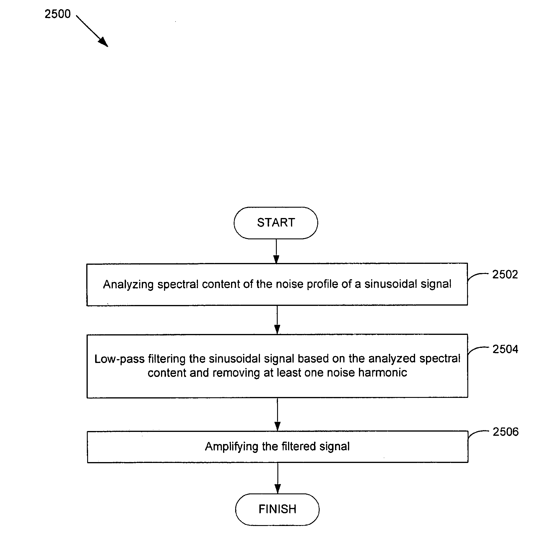
[0043] An amplifier, or a buffer, may comprise an amplifying active device with a certain level of nonlinearity, followed by a tuned stage, for example. In one aspect of the invention, a general technique for analyzing a mildly nonlinear buffer / amplifier may be developed through solving a typical implementation with long channel CMOS devices. In a different aspect of the invention, a resulting technique for reducing phase noise prior to amplification may be implemented. For example, a processor may be utilized prior to amplification by the amplifier to analyze one or more noise characteristics of an incoming signal. A filter, such as a low-pass filter, may then be utilized to filter one or more noise characteristics, such as a noise harmonic signal, from the analyzed signal prior to amplification.

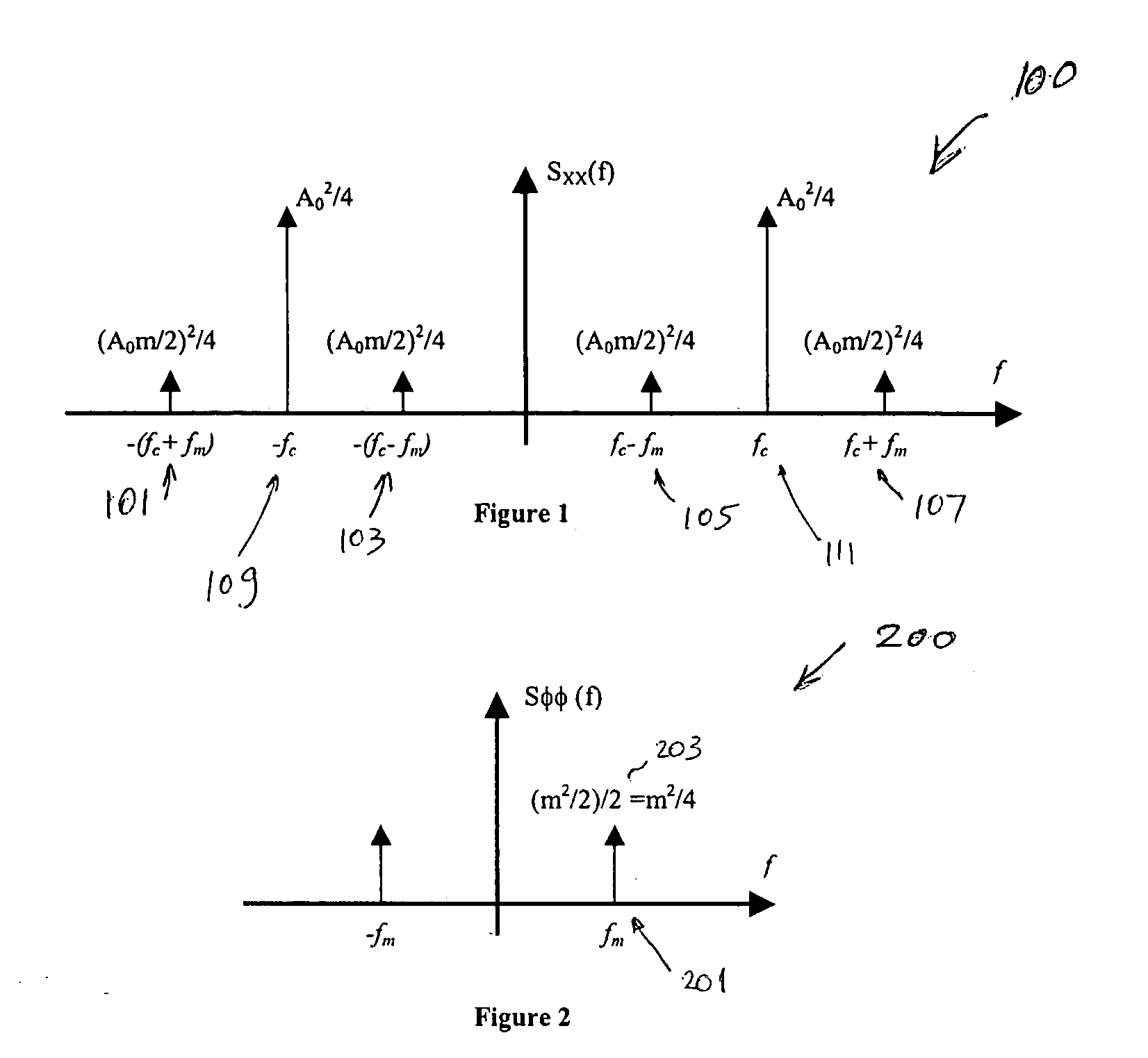
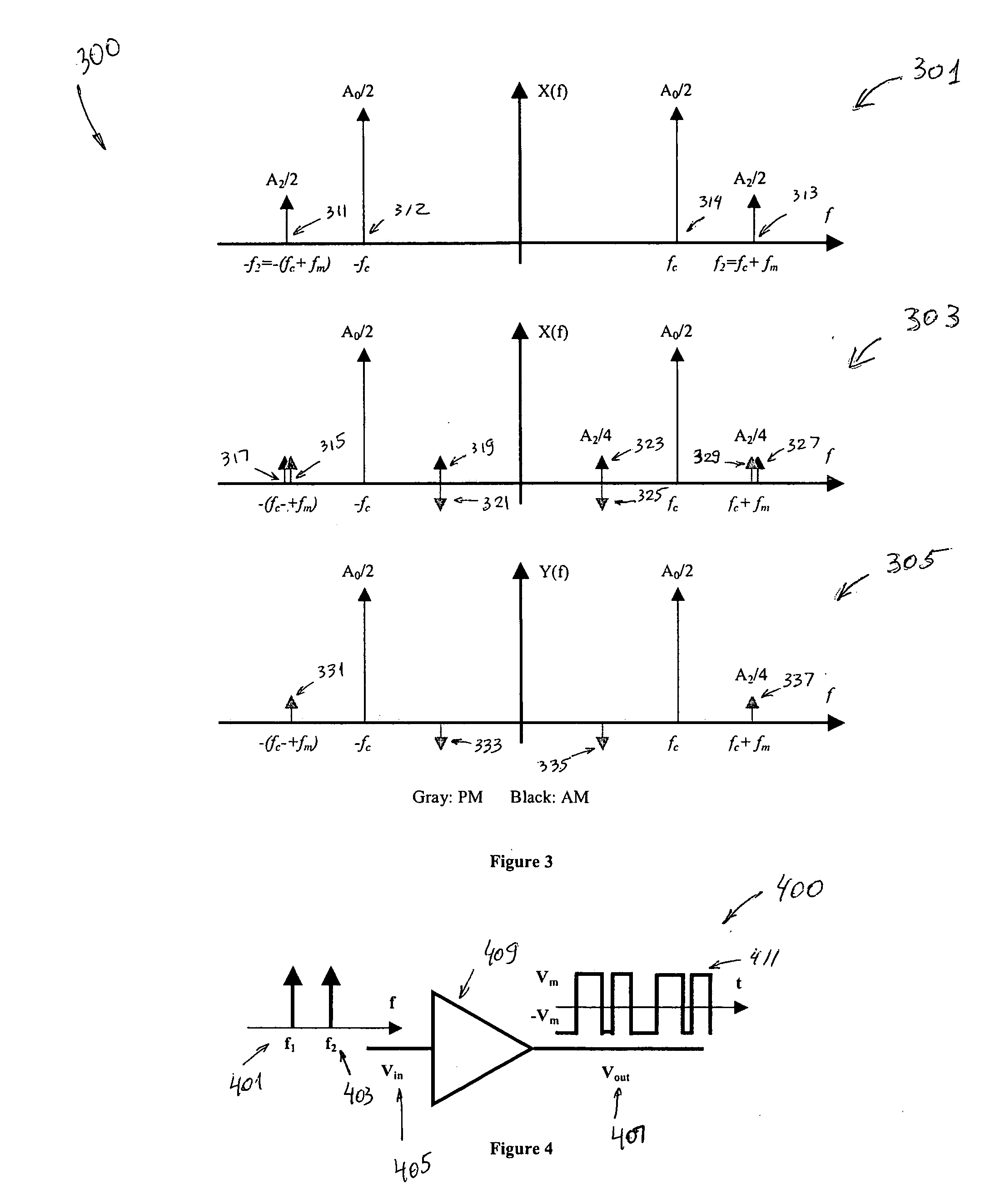
[0044] Nonlinear operations within an electric circuit, such as amplifying, may cause distortion and aliasing in the signal and noise spectrum. In particular, it may be established for a h...


PUM


Abstract

Methods and systems for processing a signal with a corresponding noise profile are disclosed. Aspects of the method may comprise analyzing spectral content of the noise profile. At least one noise harmonic within the signal may be filtered based on said analyzed spectral content. The filtered signal may be amplified. The noise profile may comprise a phase noise profile. The signal may comprise at least one of a sinusoidal signal and a noise signal. At least one filter coefficient that is used to filter the at least one noise harmonic may be determined. The filtering may comprise low pass filtering. The signal may be modulated prior to filtering. The amplifying may comprise buffering. A non-linearity characteristic of the signal may be determined and a noise harmonic may be low-pass filtered within the signal based on the determined non-linearity characteristic.

Description

RELATED APPLICATIONS [0001] The present application is a continuation-in-part of U.S. patent application Ser. No. 09 / 634,552, filed Aug. 8, 2000 which claims benefit from and priority to U.S. Patent Application Ser. No. 60 / 160,806, filed Oct. 21, 1999; Application No. 60 / 163,487, filed Nov. 4, 1999; Application No. 60 / 163,398, filed Nov. 4, 1999; Application No. 60 / 164,442, filed Nov. 9, 1999; Application No. 60 / 164,194, filed Nov. 9, 1999; Application No. 60 / 164,314, filed Nov. 9, 1999; Application No. 60 / 165,234, filed Nov. 11, 1999; Application No. 60 / 165,239, filed Nov. 11, 1999; Application No. 60 / 165,356; filed Nov. 12, 1999; Application No. 60 / 165,355, filed Nov. 12, 1999; Application No. 60 / 172,348, filed Dec. 16, 1999; Application No. 60 / 201,335, filed May 2, 2000; Application No. 60 / 201,157, filed May 2, 2000; Application No. 60 / 201,179, filed May 2, 2000; Application No. 60 / 202,997, filed May 10, 2000; Application No. 60 / 201,330, filed May 2, 2000. The above referenced ap...

Claims


Application Information

Patent Timeline
Patent Type & Authority Applications(United States)
IPC IPC(8): H03C3/09H03H11/12H03H21/00H03L7/089H03L7/099H03L7/10
CPCH03C3/245H03H11/1291H03H21/0001H03H21/0012H03L2207/06H03J2200/10H03L7/0891H03L7/099H03L7/10H03H2011/0494H03F1/26H03F3/193H03F2200/165H03F2200/399
Inventor MOLOUDI, SHERVIN
Owner AVAGO TECH INT SALES PTE LTD
Why Eureka
Try Eureka