Circuit for generating a tracking reference voltage

Inactive Publication Date: 2005-11-17
IBM CORP
View PDF4 Cites 11 Cited by
  • Summary
  • Abstract
  • Description
  • Claims
  • Application Information

AI Technical Summary

Benefits of technology

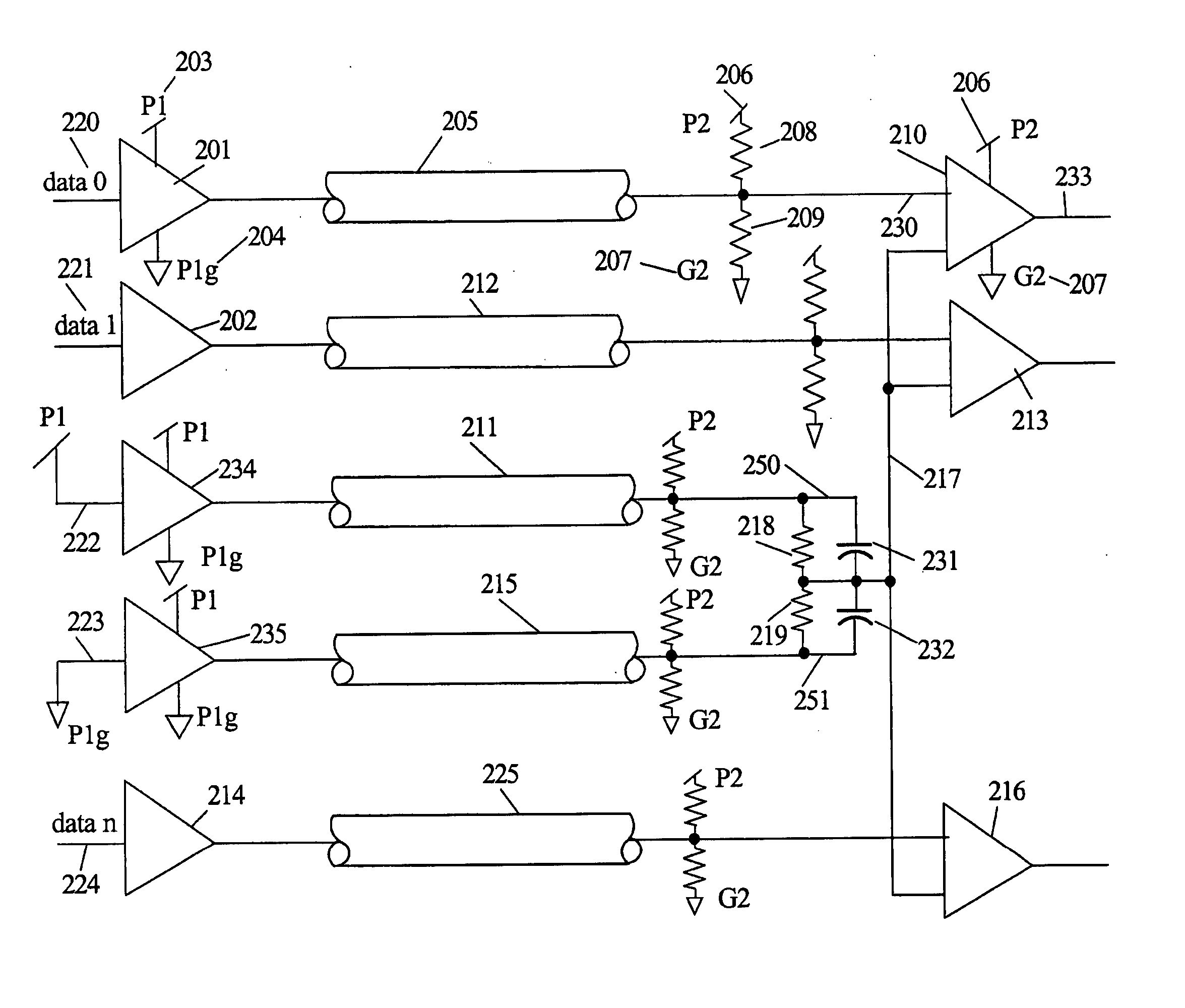
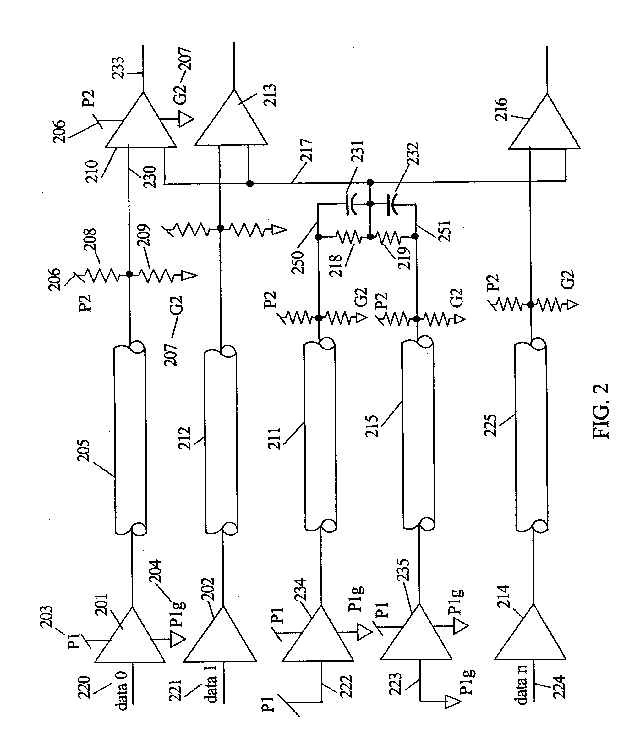
[0007] The present invention generates a derived reference voltage for use in pseudo-differential signaling wherein a driver in one integrated circuit chip generates a signal that is communicated to a receiver in another integrated circuit chip over high speed circuit transmission lines between the two integrated circuit chips. The derived reference is generated as a voltage potential between the power supply rails with a source resistance substantially equal to the source resistance of Thevenin's resistance terminators used for the data signals. A data signal driver for data signals couples power supply noise from its driver side chip power supply to its signal line and this noise propagates with a data signal to one input of its corresponding differential receiver. To generate the positive side of the derived reference for the differential receiver, a first driver like the data driver is configured to generate a direct current (DC) logic one output corresponding to the driver side chip positive pow

Problems solved by technology

Off-chip communication paths are longer, have higher noise, impedance mismatches, and have more discontinuities than on-chip communi

Method used


Image

  • Circuit for generating a tracking reference voltage
  • Circuit for generating a tracking reference voltage
  • Circuit for generating a tracking reference voltage

Examples


Embodiment Construction

[0013] In the following description, numerous specific details are set forth to provide a thorough understanding of the present invention. However, it will be obvious to those skilled in the art that the present invention may be practiced without such specific details. In other instances, well-known circuits may be shown in block diagram form in order not to obscure the present invention in unnecessary detail. For the most part, details concerning timing considerations and the like have been omitted inasmuch as such details are not necessary to obtain a complete understanding of the present invention and are within the skills of persons of ordinary skill in the relevant art.

[0014] Refer now to the drawings wherein depicted elements are not necessarily shown to scale and wherein like or similar elements are designated by the same reference numeral through the several views.

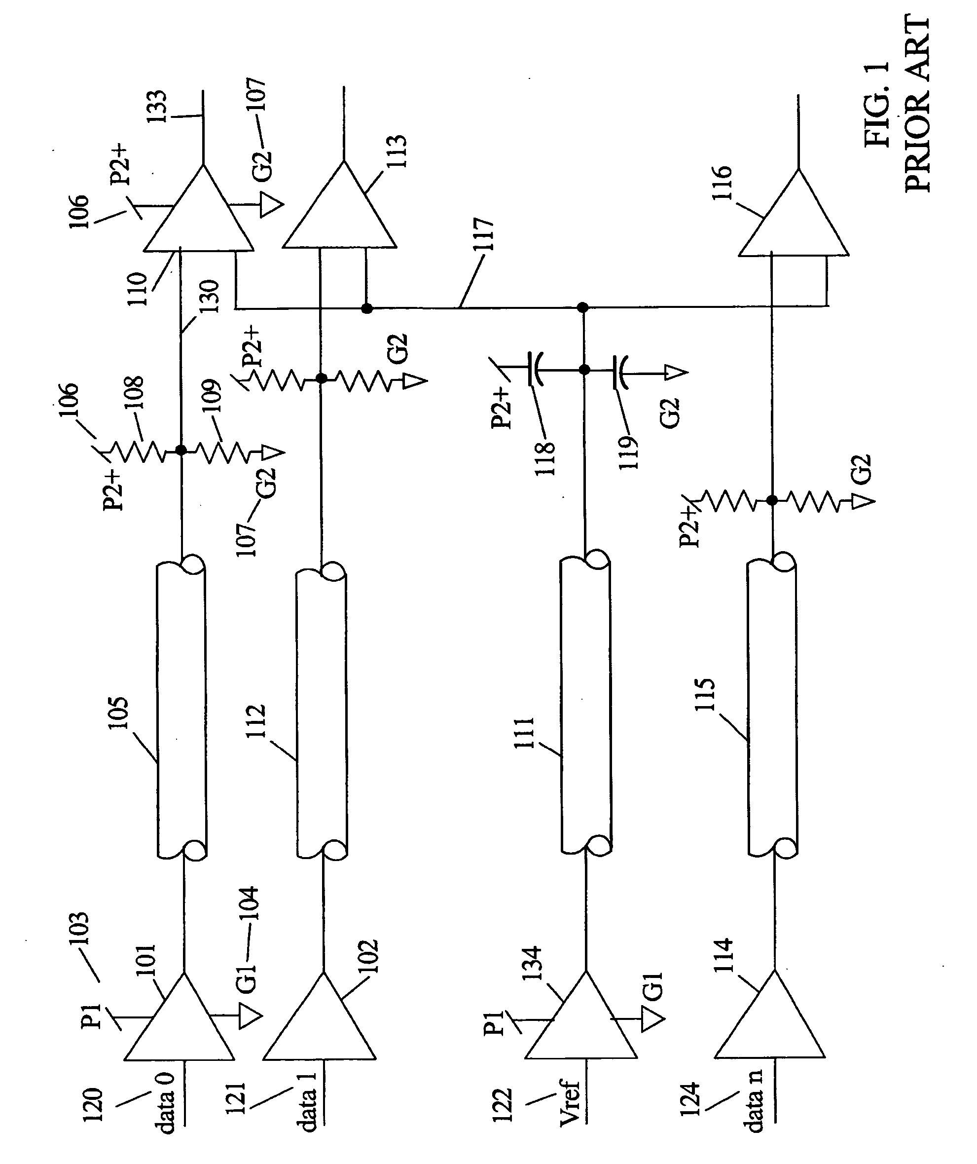
[0015]FIG. 1 is a circuit diagram of typical pseudo-differential signaling for transmitting data from a driver...


PUM


Abstract

Two or more integrated circuit (IC) chips are separated by a significant distance relative to their communication frequency such that pseudo-differential signaling is used to improve signal detection. A derived reference voltage is generated that tracks the variations of the driver and receiver side power supply variations that normally reduce noise margins. The derived reference voltage is filtered to reduce high frequency response and coupled as the reference to differential receivers used to detect the logic levels of the communication signals.

Description

TECHNICAL FIELD [0001] The present invention relates in general to board level transmission line drivers and receivers, and in particular, to references for pseudo-differential drivers and receivers. BACKGROUND INFORMATION [0002] Digital computer systems have a history of continually increasing the speed of the processors used in the system. As computer systems have migrated towards multiprocessor systems, sharing information between processors and memory systems has also generated a requirement for increased speed for the off-chip communication networks. Designers usually have more control over on-chip communication paths than for off-chip communication paths. Off-chip communication paths are longer, have higher noise, impedance mismatches, and have more discontinuities than on-chip communication paths. Since off-chip communication paths are of lower impedance, they require more current and thus more power to drive. [0003] When using inter-chip high-speed signaling, noise and coupl...

Claims


Application Information

Patent Timeline
IPC IPC(8): H03K17/16H04L25/06H04L25/45
CPCH04L25/45H04L25/061
Inventor DREPS, DANIEL M.HARIDASS, ANANDTRUONG, BAO G.
Owner IBM CORP
Why Eureka
Try Eureka