
Resonator and method for manufacturing the same

a technology of resonators and resonators, which is applied in the field of resonators, can solve the problems of increasing the ripple wave in the band of the wave filter, and affecting the performance of the resonator, so as to improve the frequency response curve of the resonator

Active Publication Date: 2020-12-31
AAC ACOUSTIC TECH (SHENZHEN) CO LTD
View PDF5 Cites 3 Cited by
  • Summary
  • Abstract
  • Description
  • Claims
  • Application Information

AI Technical Summary

Benefits of technology

The present disclosure provides a resonator with a Bragg reflector ring that improves its frequency response curve. The resonator includes a silicon substrate, bottom electrode, piezoelectric layer, top electrode and Bragg reflector ring. The Bragg reflector ring has alternating high and low acoustic impedances and can form multiple reflection surfaces that cancel out clutter waves, suppressing the parasitic mode. This results in improved frequency response curve and reduced filtering, leading to better overall performance of the resonator.

Problems solved by technology

With the development of technology, the quartz crystal resonators and ceramic resonators are not suitable for high-frequency and miniaturized products due to defects such as large volume and low frequency.
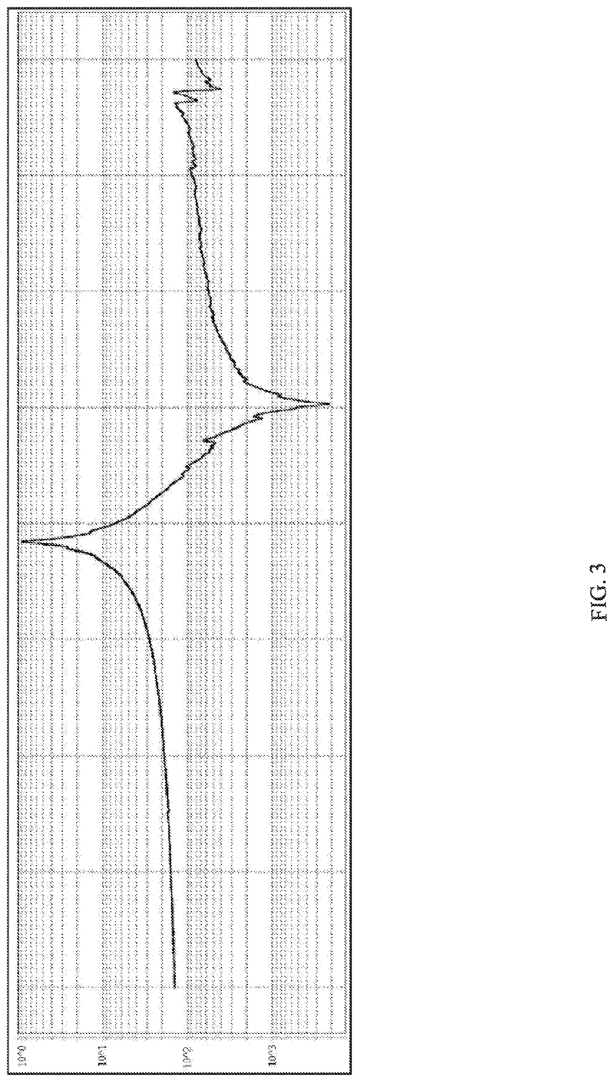
As shown in FIG. 3 and FIG. 4, the acoustic waves propagating laterally will be reflected at an edge of the top electrode, and a plurality of resonance points of clutter waves are generated in an impedance curve of the resonator, especially in the working frequency band between two resonance peaks, thereby forming parasitic mode, which causes phase fluctuation in the working frequency band, affecting the performance of the resonator and in turn increasing ripple waves in the band of the wave filter.

Method used


Image

  • Resonator and method for manufacturing the same
  • Resonator and method for manufacturing the same
  • Resonator and method for manufacturing the same

Examples


Embodiment Construction

[0037]The present disclosure will be further described below with reference to the drawings and embodiments.

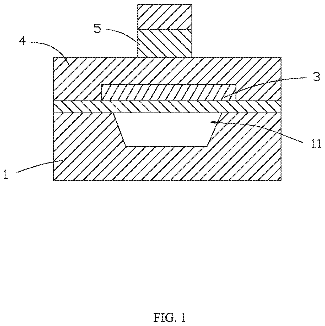
[0038]As shown in FIG. 5, a resonator according to an embodiment of the present disclosure includes a silicon substrate 1, a bottom electrode 3 stacked on a portion of the silicon substrate 1, a piezoelectric layer 4 covering the bottom electrode 3 and another portion of the silicon substrate 1, a top electrode 5 and a Bragg reflecting ring 6 stacked on the piezoelectric layer 4.

[0039]The piezoelectric layer 4 is made of an aluminum nitride film. The aluminum nitride film is an excellent piezoelectric material which has high temperature resistance, stable chemical properties, and good insulation performance. Further, the aluminum nitride film has a large electromechanical coupling coefficient, high acoustic velocity and good high-frequency performance, being suitable for making surface acoustic wave (SAW) devices.

[0040]The Bragg reflecting ring 6 is formed on a side of the pie...


PUM


Abstract

A resonator includes a silicon substrate, a bottom electrode stacked on a portion of the silicon substrate, a piezoelectric layer covering the bottom electrode and another portion of the silicon substrate, a top electrode stacked on the piezoelectric layer, and a Bragg reflecting ring. The Bragg reflecting ring is formed on a side of the piezoelectric layer connected to the top electrode and surrounds the top electrode. The Bragg reflecting ring includes a Bragg high-resistivity layer and a Bragg low-resistivity layer alternately arranged along the radial direction of the Bragg reflecting ring. An acoustic impedance of the Bragg high-resistivity layer is greater than an acoustic impedance of the Bragg low-resistivity layer. The Bragg reflecting ring forms reflection surfaces to reflect the laterally propagating clutter waves, thereby suppressing the parasitic mode in the working frequency band, improving the frequency response curve of the resonator and the overall performance of the resonator.

Description

FIELD OF THE DISCLOSURE[0001]The present disclosure relates to the technical field of resonators, and in particular to a resonator and a method for manufacturing the same.BACKGROUND OF THE DISCLOSURE[0002]Resonators are electronic components that generate resonant frequency, and are commonly divided into quartz crystal resonators and ceramic resonators. The frequency generated by the resonator has the characteristics of good stability and good anti-interference performance and is therefore widely used in various electronic products.[0003]With the development of technology, the quartz crystal resonators and ceramic resonators are not suitable for high-frequency and miniaturized products due to defects such as large volume and low frequency. Film bulk acoustic resonator (FBAR) manufactured by utilizing the longitudinal wave resonance which is excited along the thickness direction of a piezoelectric thin film material has excellent performances such as high frequency band, low power co...

Claims


Application Information

Patent Timeline
IPC IPC(8): H03H9/17H03H9/13H03H3/02
CPCH03H2003/025H03H9/13H03H9/175H03H3/02H03H9/02543H03H9/02614H03H9/0538H03H2003/023H03H9/173H03H9/02118H03H2003/021Y02D30/70
Inventor CHENG, SHIYANGWU, KELI, YANGWANG, CHAO
Owner AAC ACOUSTIC TECH (SHENZHEN) CO LTD
Learn More