Optical fiber amplifier

Inactive Publication Date: 2005-01-25
NORTEL NETWORKS LTD
View PDF4 Cites 5 Cited by
  • Summary
  • Abstract
  • Description
  • Claims
  • Application Information

AI Technical Summary

Benefits of technology

The amplifier of the invention uses a large mode field diameter fiber, which reduces the intensity for a specified output power. This results in reduced filtering of the low frequency components of the signal. The large mode field diameter worsens the bend performance of the fiber. Instead of reducing the refractive index difference to a level where the fiber is single mode at 980 nm, the refractive index difference is instead selected to provide single mode operation at the signal wavelength. In particular, the refractive index difference between the core and cladding is selected such that the fiber is multi-mode at 980 nm.
The pump source (or sources) is / are preferably in the wavelength range 1450-1500 nm in order for the fiber to provide single mode operation at the pump and signal wavelengths, although single mode operation at the pump wavelength is not essential. The operation of the amplifier is therefore closer to the cut-off wavelength, which reduces the population inversion at the edge of the core. Low intensity at the core-cladding boundary can be addressed by confining the rare earth (erbium) to the center of the core. For high power applications, the impact of this edge effect is small.

Problems solved by technology

This results in reduced filtering of the low frequency components of the signal.
The large mode field diameter worsens the bend performance of the fiber.

Method used


Image

  • Optical fiber amplifier
  • Optical fiber amplifier
  • Optical fiber amplifier

Examples


Embodiment Construction

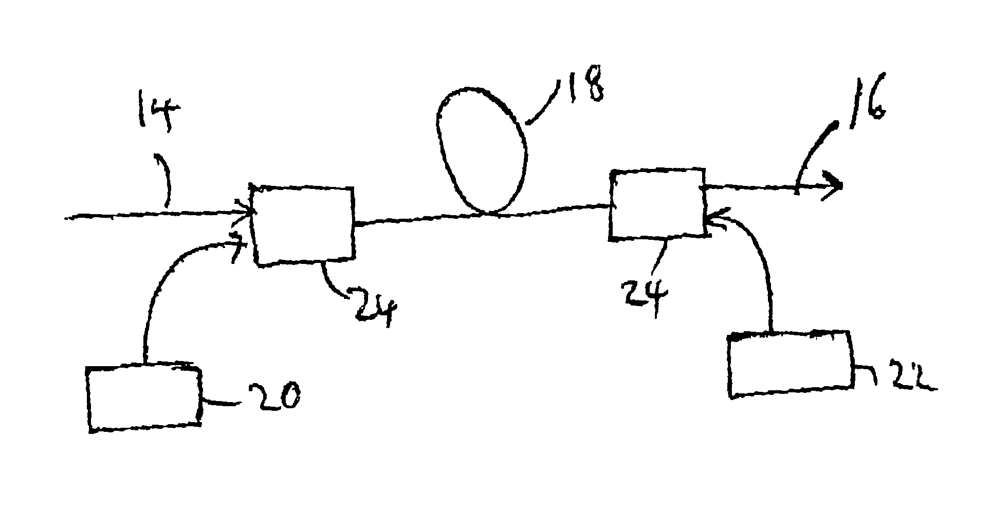
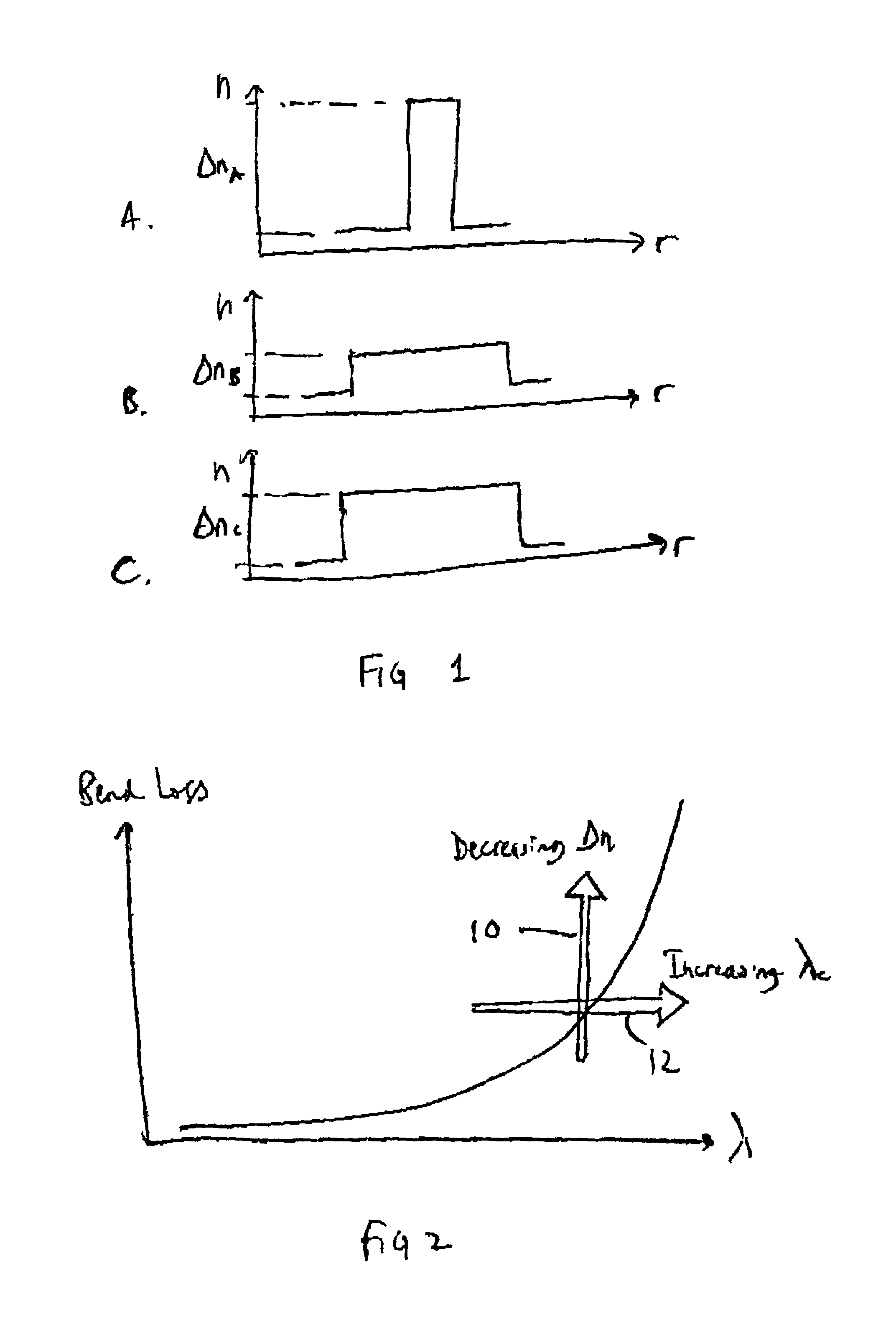
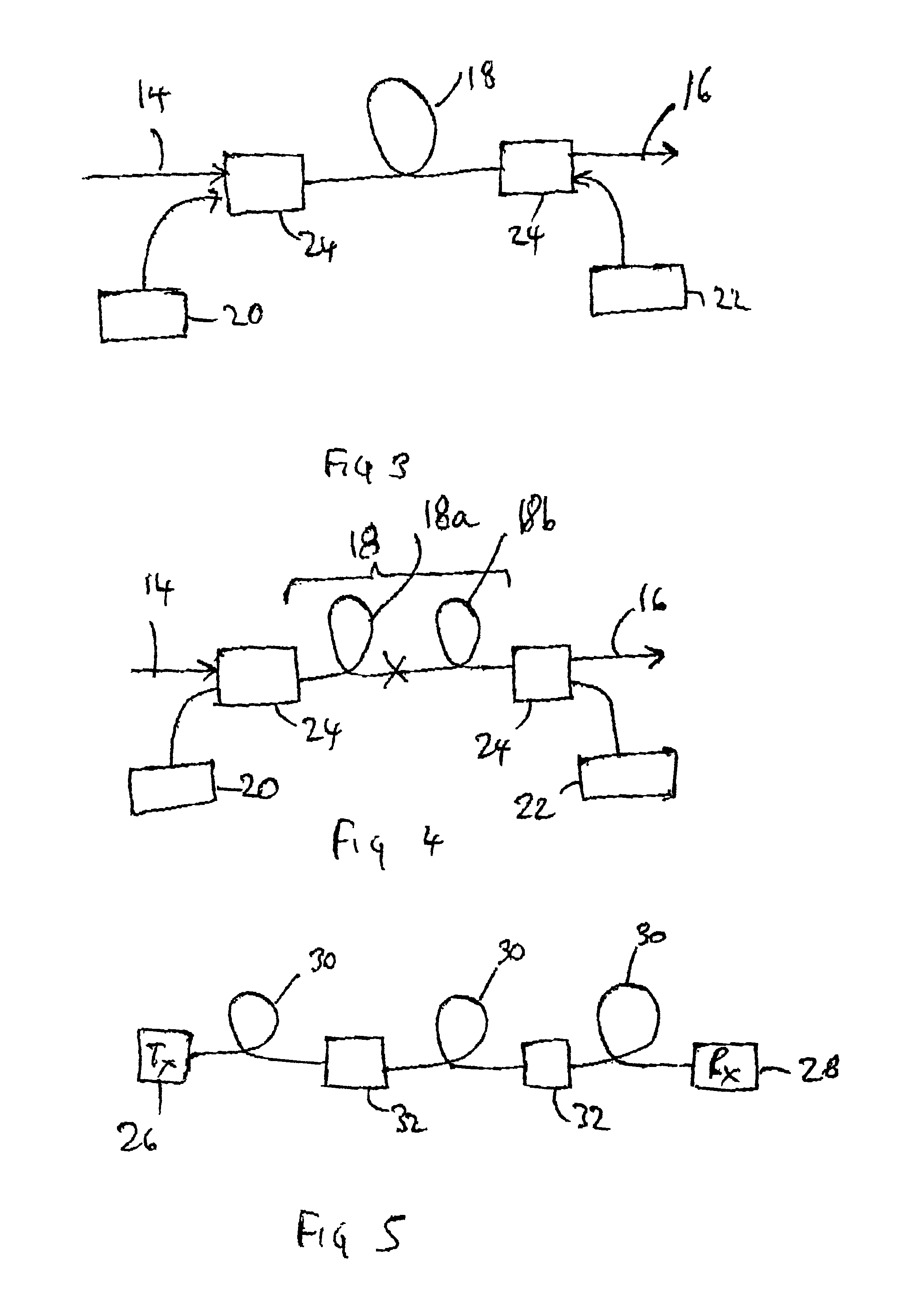
FIG. 1 shows schematically the refractive index profiles for various types of fiber. FIG. 1A shows the profile for conventional amplification fiber, in which a relatively narrow core is used, giving a mode field diameter of around 4 to 6 μm at 1550 nm. This gives low noise and high efficiency operation and also ensures single mode operation for the pump and signal wavelengths of interest. The small mode field diameter results in higher intensity signals which improve the efficiency of the amplifier. The fiber has a relatively high refractive index difference between the core and cladding.

An optical amplifier essentially has a high-pass filtering response, and one problem with the conventional fiber design used in optical amplifiers is that the small mode field diameter results in significant low frequency signal attenuation at high power levels, which can adversely affect low frequency signal components or low frequency channels, such as analogue maintenance channels.

One possible so...


PUM


Abstract

An optical amplifier comprises a doped fiber core and a cladding layer surrounding the core. The mode field diameter of the fiber is greater than 8 μm and the refractive index difference between the core and the cladding layer is selected such that the cut-off wavelength at which the fiber becomes single mode lies in the range 1000-1550 nm. This amplifier uses a large made field diameter fiber, which reduces the intensity for a specified output power. This results in reduced filtering of the low frequency components of the signal. The refractive index difference between the core and cladding is selected such that the fiber is multi-mode at 980 nm, which enables bend performance to be improved.

Description

FIELD OF THE INVENTIONThe present invention relates to optical fiber telecommunication systems and to optical fiber amplifiers which are employed in such systems.BACKGROUND OF THE INVENTIONFiber amplifiers provide gain by the stimulated emission of radiation. A fiber amplifier typically includes a gain fiber, the core of which includes active dopant ions. A signal to be amplified as well as a pump signal are provided to the fiber core, and a wavelength division multiplexer (WDM) coupler can be used for this purpose. The pump signal is typically generated by a laser diode.The amplifier gain is related to the amount of pump power coupled to the gain fiber. Also, the output power of the amplifier influences the frequency response of the amplifier to signal modulation. In particular, as the output power increases, the amplifier becomes less effective for low frequency components of the input signal. The amplifier has a high pass frequency response, which shifts towards higher frequencie...

Claims


Application Information

Patent Timeline
IPC IPC(8): H01S3/06H01S3/067
CPCH01S3/06708
Inventor ROBINSON, ALANKING, JONATHANWILSON, STEPHEN
Owner NORTEL NETWORKS LTD
Why Eureka
Try Eureka