Negative coefficient of thermal expansion particles and method of forming the same

a technology of thermal expansion particle and negative coefficient, which is applied in the direction of coupling device connection, synthetic resin layered product, non-conductive material with dispersed conductive material, etc., can solve the problem of limited extent to which the cte of a material can be thus reduced, and the improvement over siosub>2 is only moderate, so as to eliminate or reduce the problem of association

Inactive Publication Date: 2005-05-12
GLOBALFOUNDRIES INC
View PDF7 Cites 13 Cited by
  • Summary
  • Abstract
  • Description
  • Claims
  • Application Information

AI Technical Summary

Benefits of technology

[0008] An object of the invention is to eliminate or reduce the problems associated with mismatch in coefficients of thermal expansion between materials encountered in all technological applications.

Problems solved by technology

In many areas of technology, such as microelectronic packaging, there are circumstances where a mismatch of coefficient of thermal expansion (CTE) between two adjacent materials causes undesirable stresses, which can lead to interfacial failure.
However, the extent to which the CTE of a material can be thus reduced is limited.
Only limited volume percent filler can be added before properties other than CTE become significantly affected, which is often undesirable.
Most of these are anisotropic and thus can only impart the desired CTE contribution in one direction.
However, most of the volumetrically negative CTE materials have CTEs just slightly below zero ppm, at about −1 ppm, and thus the improvement over SiO2 is only moderate in light of the high cost of these materials.

Method used


Image

  • Negative coefficient of thermal expansion particles and method of forming the same
  • Negative coefficient of thermal expansion particles and method of forming the same
  • Negative coefficient of thermal expansion particles and method of forming the same

Examples


Embodiment Construction

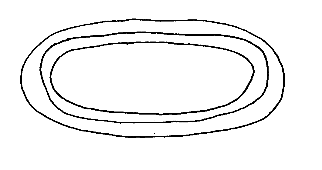
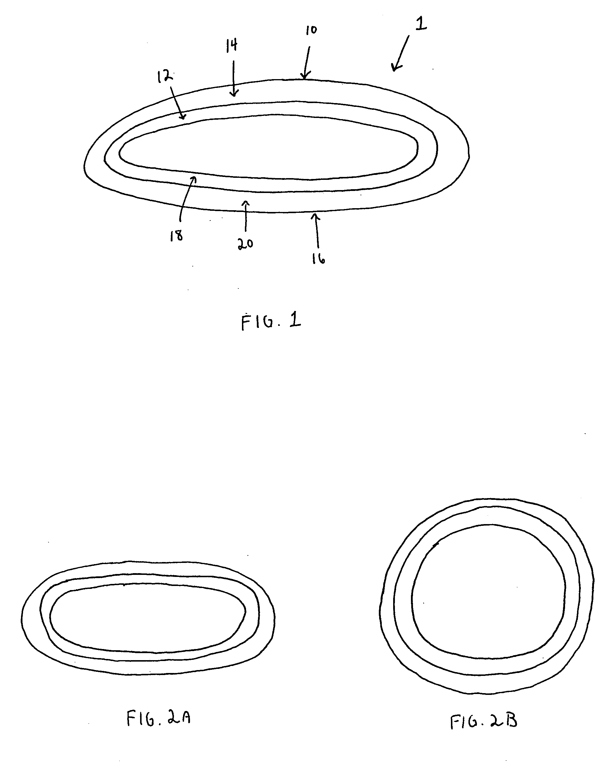
[0026]FIG. 1 is a cross sectional view of a negative CTE particle 1 according to an exemplary embodiment of the invention. The negative CTE particle 1 includes a first bilayer 10 having an inner layer 12 and an outer layer 14, and a second bilayer 16 having an inner layer 18 and an outer layer 20. The inner layer 12 of the first bilayer 10 faces the inner layer 18 of the second bilayer 16. The inner layers 12 and 18 are joined together along a perimeter of the inner layers 12 and 18, and the outer layers 14 and 20 are joined together along a perimeter of the outer layers 14 and 20. The inner layers 12 and 18 have a higher CTE than that of the outer layers 14 and 20. The bilayers 10 and 16 have adequate strength and flexibility such that they will bend elastically in response to temperature induced stress. The bilayers 10 and 16 can be formed of any suitable materials, such as, for example, metals, glass, polymers, metal oxides, carbides, nitrides, and alloys.

[0027]FIGS. 2a-2b show ...


PUM

PropertyMeasurementUnit
temperaturesaaaaaaaaaa
coefficient of thermal expansionaaaaaaaaaa
temperatureaaaaaaaaaa

Abstract

A negative coefficient of thermal expansion particle includes a first bilayer having a first bilayer inner layer and a first bilayer outer layer, and a second bilayer having a second bilayer inner layer and a second bilayer outer layer. The first and second bilayers are joined together along perimeters of the first and second bilayer outer layers and first and second bilayer inner layers, respectively. The first bilayer inner layer and the second bilayer inner layer are made of a first material and the first bilayer outer layer and the second bilayer outer layer are made of a second material. The first material has a greater coefficient of thermal expansion than that of the second material.

Description

BACKGROUND OF THE INVENTION [0001] 1. Field of the Invention [0002] The present invention relates to altering the coefficient of thermal expansion of materials, including gases, liquids and solids, and, more specifically, the introduction of filler materials into these materials to control the overall coefficient of thermal expansion. [0003] 2. Description of the Related Art [0004] In many areas of technology, such as microelectronic packaging, there are circumstances where a mismatch of coefficient of thermal expansion (CTE) between two adjacent materials causes undesirable stresses, which can lead to interfacial failure. This problem has been addressed in many ways. For example, one material can be modified by a filler material to form a composite having a CTE that is more compatible with that of an adjacent material. A simple example might be to add an SiO2 filler to epoxy glue to reduce the epoxy glue's composite CTE to be closer to that of a metal to which it will be adhered. [...

Claims


Application Information

Patent Timeline
Patent Type & Authority Applications(United States)
IPC IPC(8): B32B15/08B32B27/00H01R13/24H01R43/00H05K1/02H05K3/32
CPCB32B15/08H01R13/2414H01R43/007H05K1/0271H05K3/321Y10T428/12028H05K2201/0218H05K2201/068Y10T428/12181Y10T428/12535H05K3/325Y10T428/249971Y10T428/249974Y10T428/31609
Inventor HOUGHAM, GARETH GEOFFREYLIU, XIAO HUCHEY, S. JAYDOYLE, JAMES PATRICKZINTER, JOSEPH JR.ROOKS, MICHAEL J.SUNDLOF, BRIAN RICHARDCASEY, JON ALFRED
Owner GLOBALFOUNDRIES INC
Why Eureka
Try Eureka