
Pacemaker passive measurement testing system and method

a technology of passive measurement and pacemaker, which is applied in the field of cardiac pacemakers and implantable cardioverterdefibrillators, can solve problems such as the potential to disturb the pacing function of the pacemaker

Inactive Publication Date: 2005-05-12
CARDIAC PACEMAKERS INC
View PDF35 Cites 6 Cited by
  • Summary
  • Abstract
  • Description
  • Claims
  • Application Information

AI Technical Summary

Problems solved by technology

Others cannot, however, because to do so might affect the operation of the pacemaker.
Simply turning on an unused sensing channel has the potential to disturb the pacing function of the pacemaker since its programming will not allow the new incoming signal to be properly interpreted.

Method used


Image

  • Pacemaker passive measurement testing system and method
  • Pacemaker passive measurement testing system and method
  • Pacemaker passive measurement testing system and method

Examples


Embodiment Construction

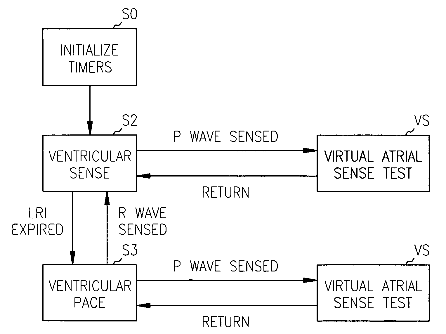
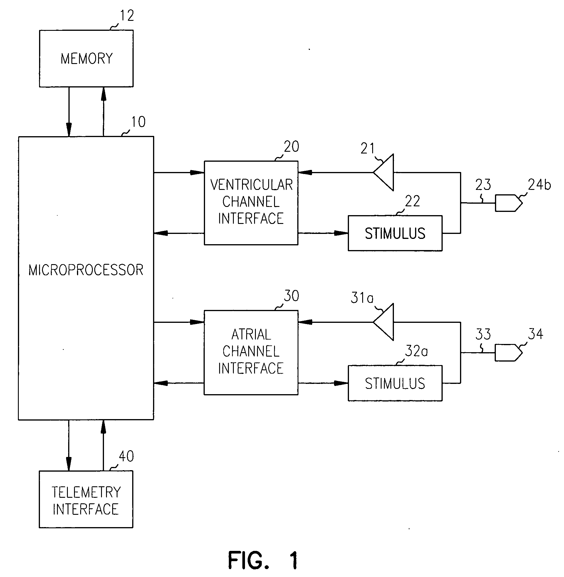
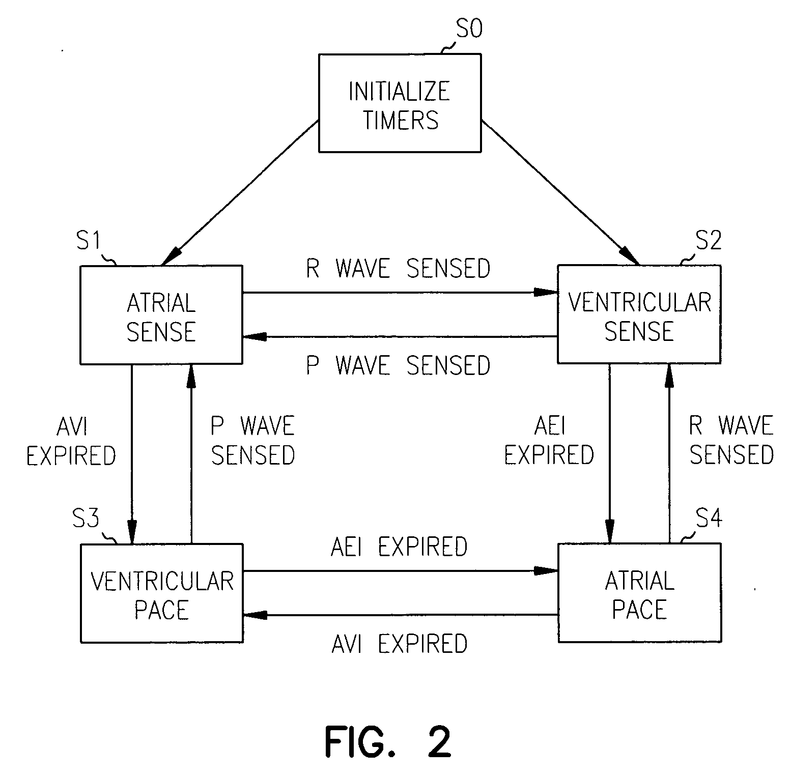
[0014] The basic function of a modern pacemaker is to deliver pacing pulses to the heart in accordance with sensed cardiac signals. Programmability of the pacemaker allows it to operate in a number of different pacing modes. The electronic circuitry for controlling the pacemaker can be either in the form of custom integrated circuits or a microprocessor based design with application specific software. Because of its inherent flexibility and the ease with which additional functionality can be added, a microprocessor-based designs is the most widely used. In the description that follows, a microprocessor-based pacemaker will be referred to as incorporating the system and method which is the present invention. It should be appreciated, however, the invention could also be incorporated into a pacemaker controlled by custom logic circuitry either in addition to or instead of a programmed microprocessor. The term “circuitry” as used herein should therefore be taken to mean either custom c...


PUM


Abstract

A system and method for passively testing a cardiac pacemaker in which sensing signal amplitudes and lead impedance values are measured and stored while the pacemaker is functioning in its programmed mode. The amplitude and impedance data may be gotten and stored periodically at regular intervals to generate a historical record for diagnostic purposes. Sensing signal amplitudes may also be measured and stored from a sensing channel which is currently not programmed to be active as long as the pacemaker is physically configured to support the sensing channel. Such data can be useful in evaluating whether a switch in the pacemaker's operating mode is desirable.

Description

CROSS-REFERENCE TO RELATED APPLICATIONS [0001] This patent application is a continuation of U.S. patent application Ser. No. 10 / 118,601, filed Apr. 8, 2002, which is a continuation of U.S. patent application Ser. No. 09 / 378,315, filed on Aug. 20, 1999, now issued as U.S. Pat. No. 6,370,432, the specification of which is incorporated herein by reference.FIELD OF THE INVENTION [0002] This invention pertains generally to the field of cardiac pacemakers and implantable cardioverter-defibrillators having a pacemaking function. In particular, the invention relates to a system and method for testing selected operating parameters in an implanted pacemaker. BACKGROUND [0003] As pacemaker technology has developed, a number of standard operating modes have been developed which define how the device paces the heart. These modes are usually described by a three-letter code developed by the Inter-Society Commission for Heart Disease where each letter in the code refers to a specific function of t...

Claims


Application Information

Patent Timeline
Patent Type & Authority Applications(United States)
IPC IPC(8): A61N1/37
CPCA61N1/3706A61N1/3702
Inventor CONLEY, VICKIE L.GILKERSON, JAMES O.PERSCHBACHER, DAVID L.
Owner CARDIAC PACEMAKERS INC
Learn More