Radio frequency lighting control system programming device and method

Active Publication Date: 2005-05-12
LUTRON TECH CO LLC
View PDF8 Cites 57 Cited by
  • Summary
  • Abstract
  • Description
  • Claims
  • Application Information

AI Technical Summary

Benefits of technology

[0022] According to a feature of the present invention, lighting control system setup need not be achieved by manually programming at each device location. In addition, a given individual may complete the system setup even though not present during system installation.
[0023] According to another feature of the present invention, lighting control device behavior can be changed which would not otherwise be accessible. For example, a lighting control device setting can be changed using the programming device according to the present invention that is not modifiable through direct interaction with system components. If a setting is made accidentally, for instance, the programming device can readily reset the setting to overcome problems resulting from the accidental setting.
[0024] According to another feature of the present invention, programming time and complexity is reduced. Because devices are placed in a known condition, only programming changes need be made, rather than a complete system reprogramming. Without knowing the state of the devices, the complete reprogramming would be needed, taking 2 to 3 times longer than the programming changes alone. The known condition occurs when the devices are activated into the system. The activation process is provided to give addresses to the dev

Problems solved by technology

The identification of devices to be programmed reduces

Method used


Image

  • Radio frequency lighting control system programming device and method
  • Radio frequency lighting control system programming device and method
  • Radio frequency lighting control system programming device and method

Examples


Embodiment Construction

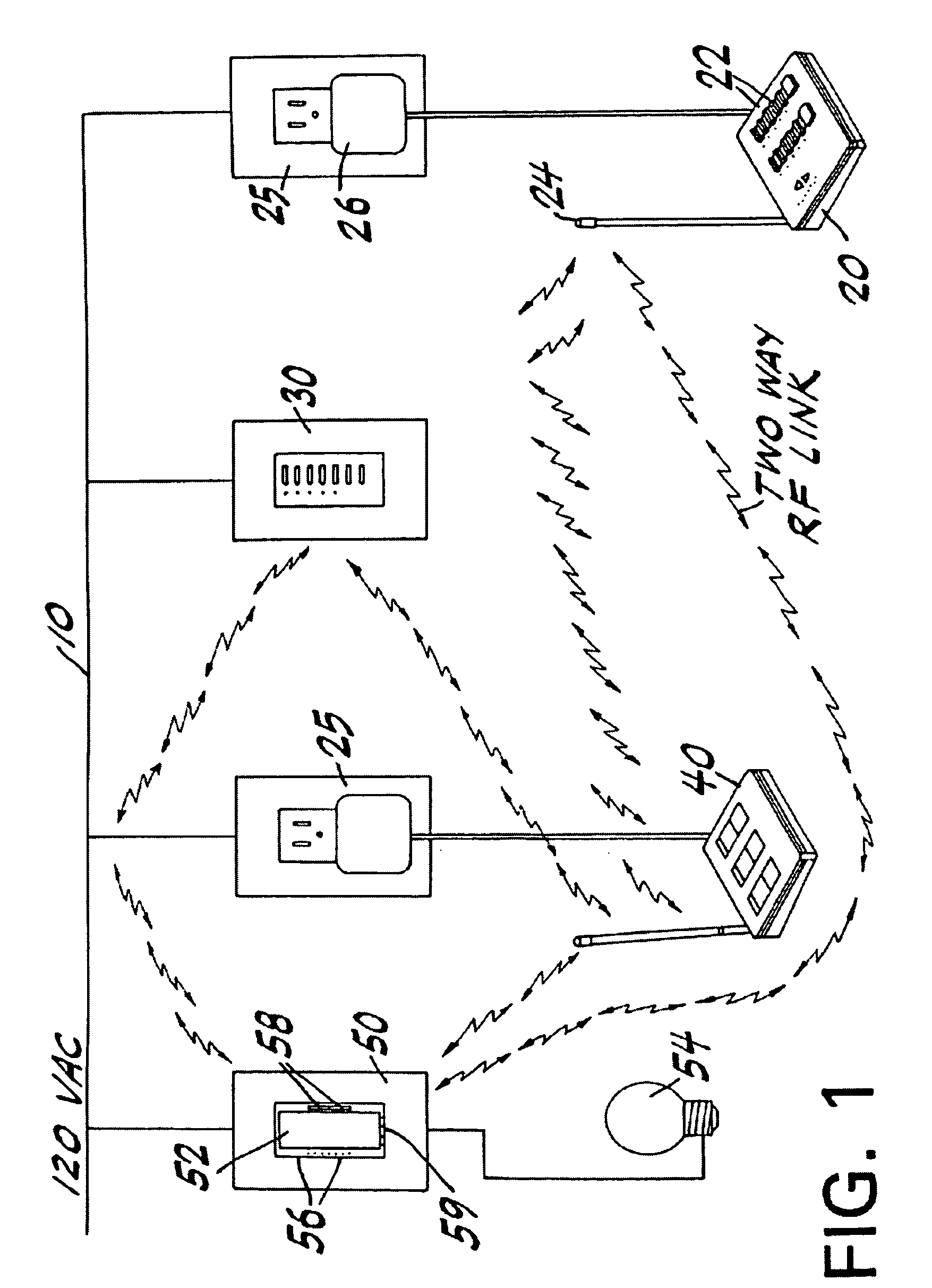
[0033] The device and method according to the present invention uses RF communications through an eavesdropping function to prepare programming setup for a distributed control system. Although the present invention describes specific embodiments that include a wireless communication configuration for a lighting control system, any type of control system in which communication between devices takes place should be considered to be within the scope of the invention. For example, the present invention may be used with control systems that communicate through hard wired connections, fiber optic cables, infra red and so forth. In the case of hard-wired communication, the communication pathway may be a power-wiring network, for example. In addition, the present invention is not limited to lighting control systems, but is also applicable to security systems, HVAC controls, or any programmable control system in which the components are able to communicate. Any of these systems may use wirel...


PUM


Abstract

An independent radio frequency programming device automates a setup process for a lighting system with lighting control devices and master controls. The programming device intercepts communications between the lighting control devices and the master control during an initial setup phase. A start function permits the programming device to provide automated setup information to the master controls. Once the automated setup process completes, the lighting system is fully programmed with behavior functions for all lighting control devices.

Description

BACKGROUND OF THE INVENTION [0001] 1. Field of the Invention [0002] The present application relates generally to a device for programming a lighting system, and relates more specifically to a device for automatically setting up a lighting preference for an automated programmable lighting system. [0003] 2. Description of the Related Art [0004] Lighting systems that use radio frequency (RF) signals to communicate with lighting controls are well known. For example, a radio frequency lighting control system is described in U.S. Pat. Nos. 5,848,054, 5,838,226 and 5,905,442. Those patents describe a central system for controlling electrical devices such as electric lamps in a building structure from remote locations through, e.g., radio frequency links. [0005] In those patents, a system for controlling the status of electrical device, for example, electric lamps, from a remote location via communication links such as radio frequency links, power line carrier links or infrared links, is de...

Claims


Application Information

Patent Timeline
IPC IPC(8): H05B37/02
CPCH05B37/0272H05B47/19H05B47/195
Inventor KRUSE, GLEN ANDREWCRAZE, JASON DOUGLASSWALKO, ROBERT FRANCIS JR.
Owner LUTRON TECH CO LLC
Why Eureka
Try Eureka