Automated door assembly system and method

a door and door assembly technology, applied in the field of door making methods, can solve the problems of high labor intensity, high cost, and subject to quality variations, and achieve the effects of improving quality, improving production efficiency, and improving production efficiency

Inactive Publication Date: 2005-05-19
MASONITE CORP
View PDF18 Cites 19 Cited by
  • Summary
  • Abstract
  • Description
  • Claims
  • Application Information

AI Technical Summary

Benefits of technology

[0008] The present invention is directed to a method of making a door. An interior side of a first facing is coated with quick acting adhesive. A doorframe is placed on the coated interior side about the periphery of the first facing. The frame is then coated with quick acting adhesive. An interior side of a second facing is placed on the coated frame. The facings and frame are compressed, thereby forming a door.
[0009] The present invention is also directed to a system for making a door. The system includes first and second stations, each for receiving a plurality of door facings. A conveyor operably associated with the first station receives and transports in a first direction an exterior surface of a door facing. A third station operably associated with the conveyor applies quick acting adhesive on an interior surface of the door facing. A fourth station operably associated with the conveyor positions a doorframe onto the adhesive covered interior surface of the door facing. A fifth station operably associated with the conveyor applies quick acting adhesive on the doorframe. A transfer mechanism operably associated with the second station positions an interior surface of a facing from the second station onto the adhesive covered doorframe. A compression station operably associated with the conveyor compresses the facings and the doorframe, thereby forming a door.

Problems solved by technology

Manual assembly of molded doors is relatively labor intensive, expensive, and subject to quality variations.
However, the production equipment necessary is often very expensive, and the methods used overly complex.
Production capability from a single manufacturing facility is often limited.
In addition, the glues used typically require curing presses, which are relatively expensive.
Furthermore, such glues require a relatively long period of time before green strength is achieved, as well as a relatively long period of time before maximum cure strength is achieved, which is impractical in an automated production system.
As such, conventional systems and methods for automated door assembly have not proven to be cost efficient.

Method used


Image

  • Automated door assembly system and method
  • Automated door assembly system and method
  • Automated door assembly system and method

Examples


Embodiment Construction

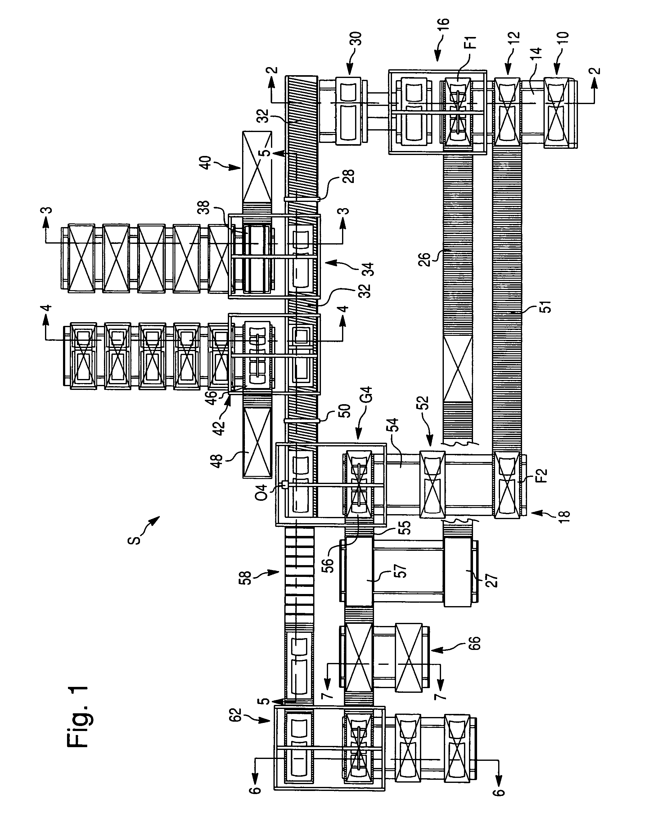
[0017] A preferred facility layout of a system S for making doors according to the present invention is best shown in FIG. 1. System S includes a loading station 10 for receiving door facings. Pallet loads of door facings may be transported to loading station 10 by fork truck. For example, each pallet load may include 200 door facings. From loading station 10, pallets may be transported to a distribution station 12 via a loading conveyor 14.

[0018] From distribution station 12, pallets are transported to either a first station 16 for processing a first door facing F1 of a door being manufactured, or a second station 18 for processing a second door facing F2 on the opposing side of the door. Preferably, the first three pallets of door facings received at distribution station 12 are directed to first station 16. The next three pallets of door facings received at distribution station 12 are directed to second station 18. Door facings F1, F2 may be made from a wood fiber composite, hard...


PUM

PropertyMeasurementUnit
timeaaaaaaaaaa
timeaaaaaaaaaa
stack down timeaaaaaaaaaa

Abstract

The present invention is directed to a method of making a door having first and second door facings and an internal doorframe. An interior side of a first facing is coated with quick acting adhesive. A frame is placed on the coated interior side about the periphery of the first facing. The frame is then coated with quick acting adhesive. An interior side of a second facing is placed on the coated frame. The facings and frame assembly are then compressed to form a door. The present invention also provides for an automated system of making the door.

Description

CROSS REFERENCE TO RELATED APPLICATION AND CLAIM TO PRIORITY [0001] This application claims priority of provisional application Ser. No. 60 / 502,982 filed Sep. 16, 2003, the disclosure of which is incorporated herein by reference and priority to which is claimed pursuant to 35 U.S.C.§ 120.FIELD OF THE INVENTION [0002] The present invention is directed to a method of making a door having first and second door facings and an internal doorframe. An interior side of the first facing is coated with quick acting adhesive. The frame is placed on the coated interior side about the periphery of the first facing. The frame is then coated with quick acting adhesive. An interior side of the second facing is placed on the coated frame. The facing and frame assembly are then compressed to form a door. The present invention also provides for an automated system of making the door. BACKGROUND OF THE INVENTION [0003] Molded doors are assembled using two door facings, often molded from a wood fiber / re...

Claims


Application Information

Patent Timeline
Patent Type & Authority Applications(United States)
IPC IPC(8): E04B1/00
CPCB62D65/06Y10T156/1761Y10T156/1089Y10T156/10Y10T156/108Y10T156/1744B27M3/18B27D5/003B32B2607/00B32B37/1284B32B37/18B32B2419/00E06B3/70E06B2003/7049E06B2003/7059E06B3/72
Inventor TYLER, KENNETH CHARLES
Owner MASONITE CORP
Why Eureka
Try Eureka