Spinal implant

a technology of spine and implant, applied in the field of spine implants, can solve the problems of destabilizing the spinal column, pain and/or nerve damage, and altering the natural separation distance between adjacent vertebrae,

Inactive Publication Date: 2003-07-24
ZIMMER SPINE INC
View PDF38 Cites 575 Cited by
  • Summary
  • Abstract
  • Description
  • Claims
  • Application Information

AI Technical Summary

Problems solved by technology

Partial or full removal of an intervertebral disc may destabilize the spinal column.
Destabilization of a spinal column may result in alteration of a natural separation distance between adjacent vertebrae.
Excessive pressure applied to the nerves may cause pain and / or nerve damage.
Spinal surgery may be complex due in part to the proximity of the spinal cord and / or the cauda equina.

Method used


Image

  • Spinal implant
  • Spinal implant
  • Spinal implant

Examples


Embodiment Construction

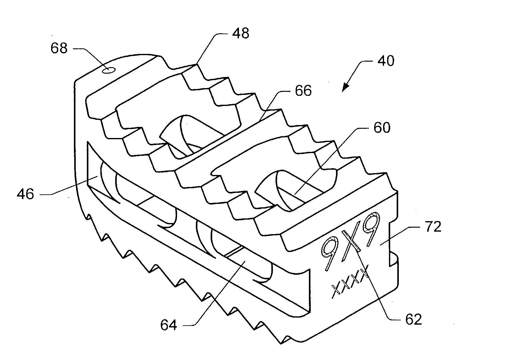
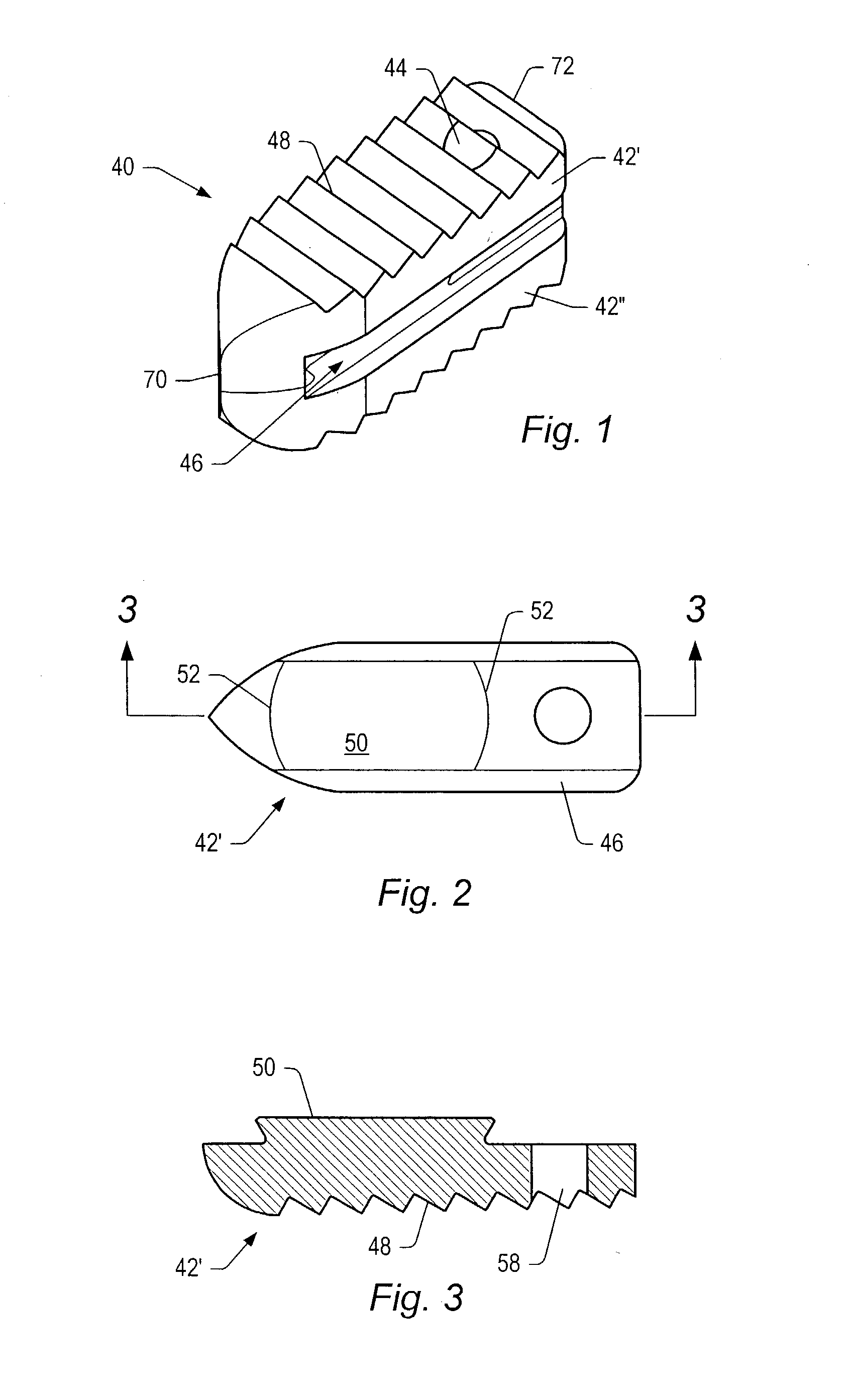
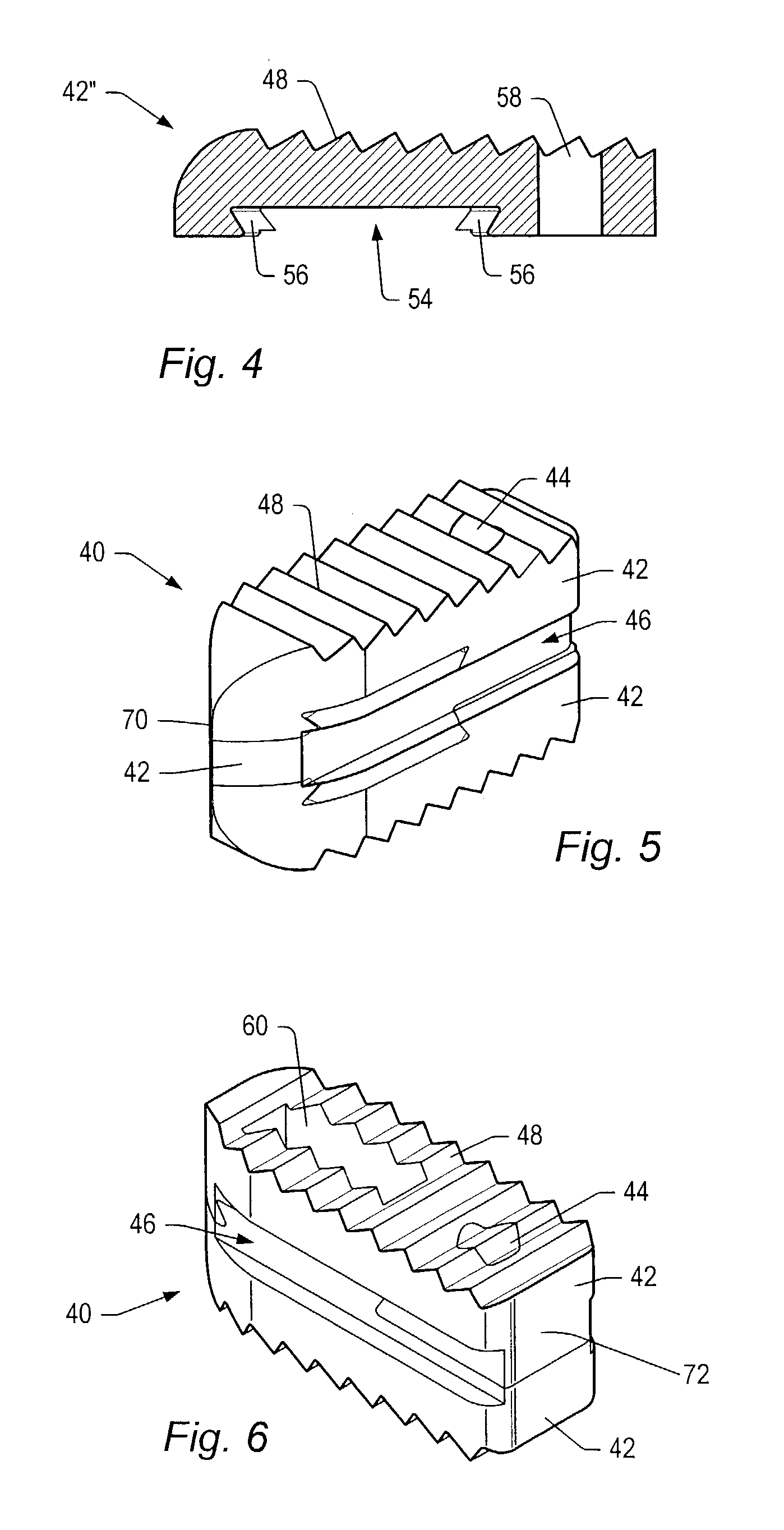
[0060] FIGS. 1-13 show embodiments of implants 40 and portions of implants that may be used to promote bone fusion. Implants 40 may be spinal implants, such as, but not limited to, posterior lumbar interbody fusion (PLIF) spinal implants. A spinal implant may establish a desired separation distance between adjacent vertebrae. In some implant embodiments, implants have surfaces made of bone or bone growth promoting material (e.g., hydroxyapatite or titanium plasma spray) that promotes fusion of the implants to vertebrae. In some embodiments, implants may include openings. The openings may be packed with bone graft or other bone growth material that promotes bone growth from vertebrae into the implant to fuse the implant to the vertebrae.

[0061] As depicted in FIG. 1, implant 40 may include members 42, fastener 44, side grooves 46, and serrations or ridges 48. An implant may include two or more members 42. Members 42 may be joined together to form implant 40. In some embodiments, membe...


PUM

PropertyMeasurementUnit
lordotic angleaaaaaaaaaa
angular rotationaaaaaaaaaa

Abstract

A spinal implant may be made of two or more implant members. In an embodiment, implant members may be joined together by a rotational connection that inhibits separation of the members as well as axial movement of the members relative to each other. Implant members may be coupled together by a pin or pins, adhesive, or other fasteners to inhibit separation and / or rotation of the members relative to each other.

Description

PRIORITY CLAIM[0001] This application claims priority to U.S. Provisional Application No. 60 / 338,321 entitled "Spinal Implant", filed Nov. 9, 2001. The above-referenced provisional application is incorporated by reference as if fully set forth herein.[0002] 1. Field of the Invention[0003] The present invention generally relates to the field of bone implants and more particularly to spinal implants. Spinal implant embodiments may stabilize and / or fuse together vertebrae. Some spinal implant embodiments may be inserted during a posterior lumbar interbody fusion procedure.[0004] 2. Description of Related Art[0005] An intervertebral disc may degenerate. Degeneration may be caused by trauma, disease, and / or aging. An intervertebral disc that becomes degenerated may have to be partially or fully removed from a spinal column. Partial or full removal of an intervertebral disc may destabilize the spinal column. Destabilization of a spinal column may result in alteration of a natural separati...

Claims


Application Information

Patent Timeline
Patent Type & Authority Applications(United States)
IPC IPC(8): A61B17/02A61B17/16A61B17/88A61B19/00A61F2/00A61F2/02A61F2/28A61F2/30A61F2/44A61F2/46
CPCA61B17/0206A61F2310/00359A61B17/1604A61B17/1671A61B17/88A61B2017/0256A61B2019/462A61F2/28A61F2/30965A61F2/4455A61F2/447A61F2/4611A61F2002/2835A61F2002/30062A61F2002/3008A61F2002/30331A61F2002/30387A61F2002/30433A61F2002/30492A61F2002/305A61F2002/30777A61F2002/30785A61F2002/30789A61F2002/3082A61F2002/30904A61F2002/30924A61F2002/30952A61F2002/4627A61F2210/0004A61F2220/0025A61F2220/0033A61F2220/0041A61F2250/0098A61F2310/00017A61F2310/00023A61F2310/00293A61F2310/00616A61F2310/00796A61B17/025A61F2002/30922A61B2090/062
Inventor GARCIA, JAVIERWAGNER, ERIK J.KRUEGER, DAVID J.
Owner ZIMMER SPINE INC
Why Eureka
Try Eureka