Lower die assembly in pressing machine

Inactive Publication Date: 2005-05-19
KUBOTA IRON WORKS
View PDF12 Cites 19 Cited by
  • Summary
  • Abstract
  • Description
  • Claims
  • Application Information

AI Technical Summary

Benefits of technology

[0007] With the forgoing taken into account, the present invention has an object aimed at providing an improved lower die assembly for use in a pressing machine, which allows a lower die or die set (hereinafter referre

Problems solved by technology

Consequently, it has been time-consuming to change die sets each having a plurality of die members

Method used


Image

  • Lower die assembly in pressing machine
  • Lower die assembly in pressing machine

Examples


Example

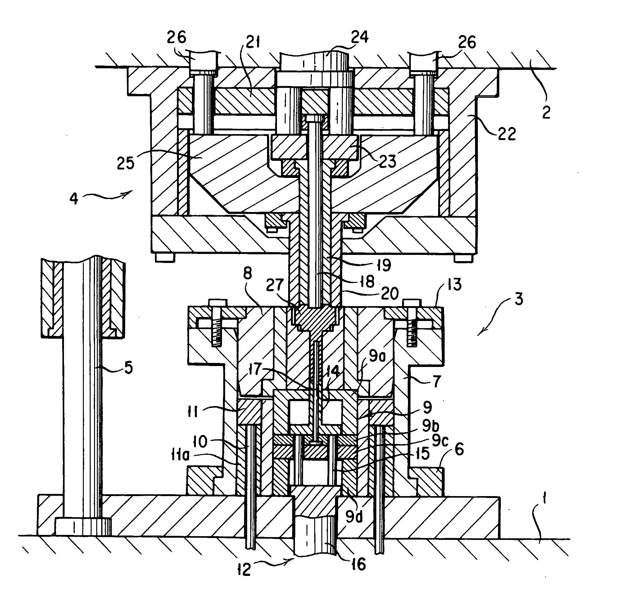
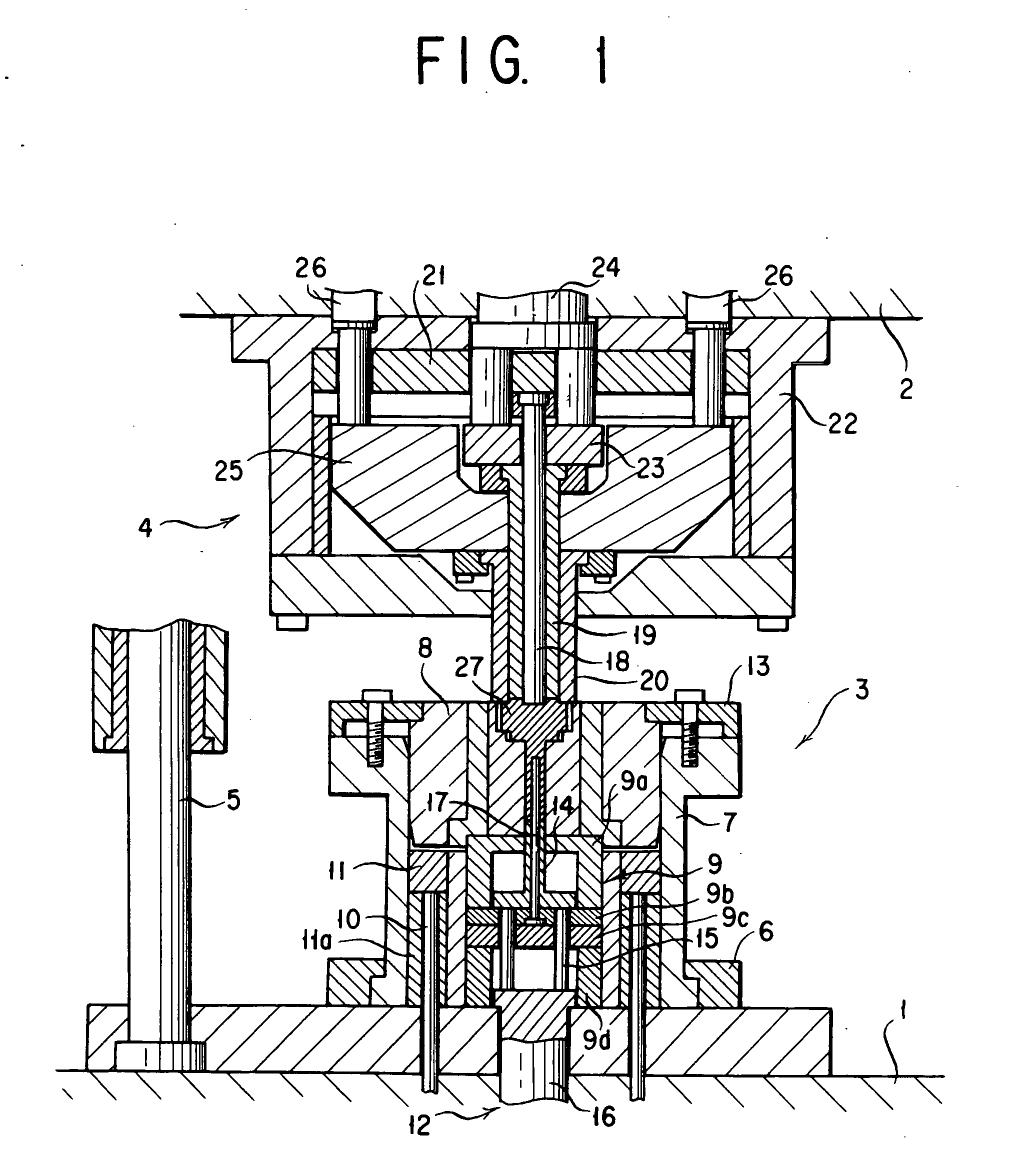
[0012] An explanation is now given of a form of implementation of the present invention with reference to the Drawing Figure. In the Figure there are shown a bolster 1, a slide 2, a lower die assembly or unit 3 fastened to an upper surface of the bolster 1, an upper die assembly or unit 4 fastened to a lower surface of the slide 2, and a guide post 5 for guiding the upper die unit 4 vertically up and down relative to the lower die unit 3.

[0013] The lower die unit 3 as shown comprises a die holder 7 fastened to the bolster 1 by means of a fastening member 6, a lower die 8 received in the die holder 7 slidably up an down to be tight-fitted therein, a set pedestal 9 for setting the lower die 8 at a predetermined height in the die holder 7, a lifting plate 11 supported on a stand 11a to 11e opposed to the lower surface of the lower die 8, a lower part forming unit 12 disposed inside of the set pedestal 9 beneath the lower die 8 and which closes the lower side of a lower die cavity of t...


PUM


Abstract

An improved lower die assembly is provided which allows a given lower die in a pressing machine to be replaced with another easily and in a short period of time relative to a die holder. In the lower die assembly in which a lower die is received and securely held in a die holder, the improvement comprises: a clamp means whereby the lower die when unclamped is received in the die holder so that the lower die can be extracted from the die holder upwards and then when clamped is securely held therein; and a lift means disposed below the lower die and whereby the lower die when unclamped is raised above an upper end of the die holder.

Description

BACKGROUND OF THE INVENTION [0001] 1. Field of the Invention [0002] The present invention relates to a lower die assembly for use in a pressing machine. [0003] 2. Description of the Prior Art [0004] In a pressing machine, especially for cold forging, a lower die or die set is typically received in a die holder anchored to a bolster. [0005] The conventional lower die arrangement has had a design such that a lower die set is received and securely held in the die holder that can be decomposed into a plurality of holder segments. When the die set is taken out of the die holder for the alteration of a formed product, it has been necessary to unclamp the die set from the die holder and then to hang and move one by one die members that make up the die set with a chain hoist or the like. [0006] Consequently, it has been time-consuming to change die sets each having a plurality of die members from one to another, and it has also been laborious and cumbersome to set about such a requirement. ...

Claims


Application Information

Patent Timeline
IPC IPC(8): B21D37/10
CPCB21D37/10
Inventor YAMANAKA, SHIGEAKIKAZAMA, TAKESHI
Owner KUBOTA IRON WORKS
Why Eureka
Try Eureka