
Pressure sensor having sensor chip and signal processing circuit mounted on a common stem

a sensor chip and sensor technology, applied in the field of sensors, can solve problems such as complex sensor structur

Inactive Publication Date: 2005-05-19
DENSO CORP
View PDF1 Cites 35 Cited by
  • Summary
  • Abstract
  • Description
  • Claims
  • Application Information

AI Technical Summary

Benefits of technology

The present invention provides an improved sensor for detecting physical amounts such as pressure. The sensor is compact as a whole because the circuit board for processing sensor signals is positioned perpendicularly to the sensor chip. The sensor chip is mounted on a thin diaphragm that is distorted by pressure applied thereto, and the opening from which pressure is introduced is formed at the other axial end of the cylindrical stem. The sensor chip is connected to the circuit board with glass having a low melting point, and the circuit board is mounted on a flat side surface formed on the outer periphery of the cylindrical stem. The sensor chip and circuit board are covered with insulating gel, and the sensor chip may be mounted on a depressed portion formed on an insulator which is connected to the side surface of the cylindrical stem with adhesive. The axial end of the cylindrical stem having the opening is hermetically connected to a structure containing a pressure to be detected, and the diaphragm is distorted by the pressure applied thereto. The sensor chip outputs an electrical signal corresponding to the distortion of the diaphragm, and the sensor output is processed by the circuit board. The pressure sensor size in the radial direction of the cylindrical stem can be made small, and the pressure sensor as a whole can be made compact.

Problems solved by technology

This positioning also makes the sensor structure complex.

Method used


Image

  • Pressure sensor having sensor chip and signal processing circuit mounted on a common stem
  • Pressure sensor having sensor chip and signal processing circuit mounted on a common stem
  • Pressure sensor having sensor chip and signal processing circuit mounted on a common stem

Examples


Embodiment Construction

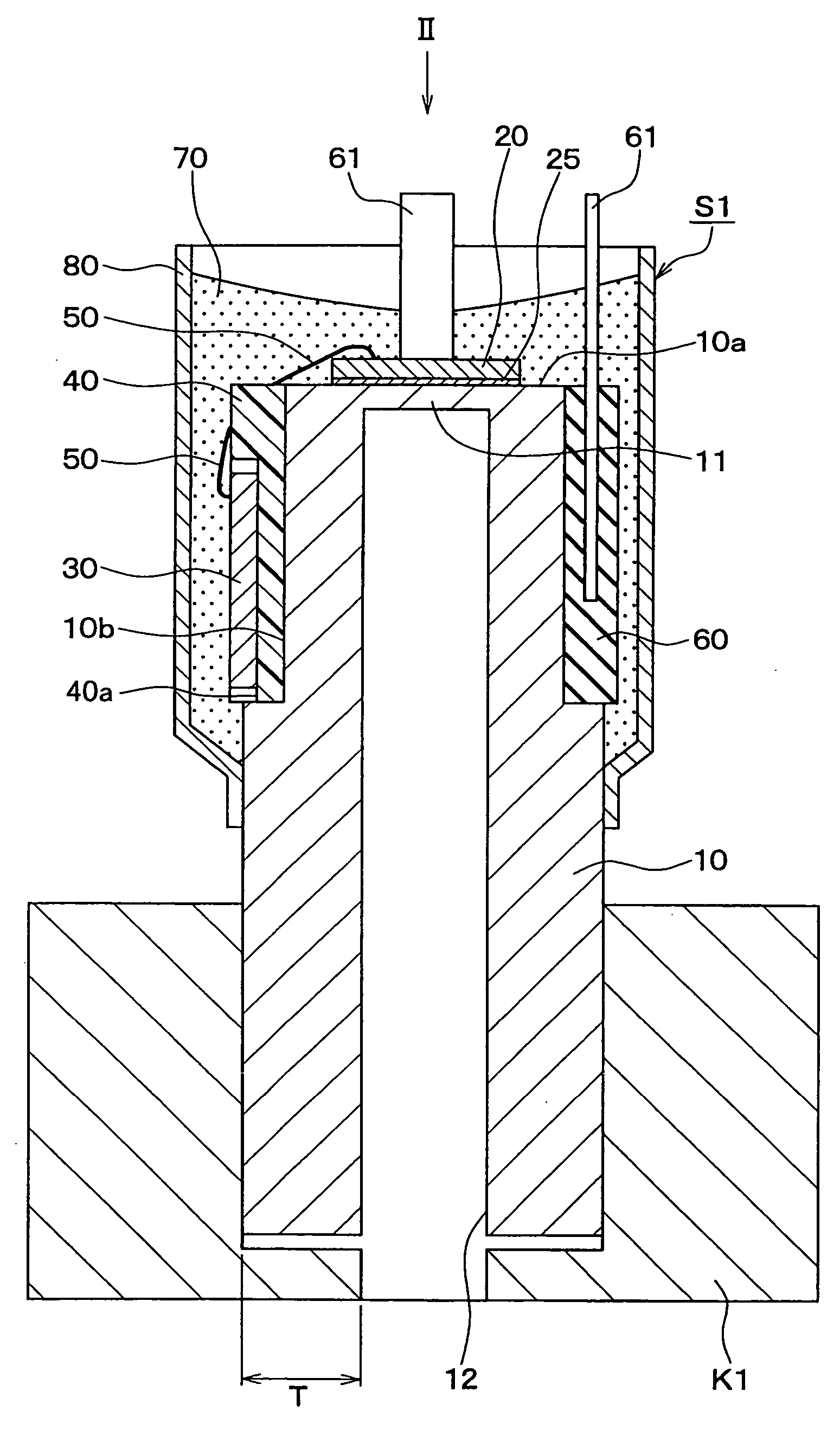
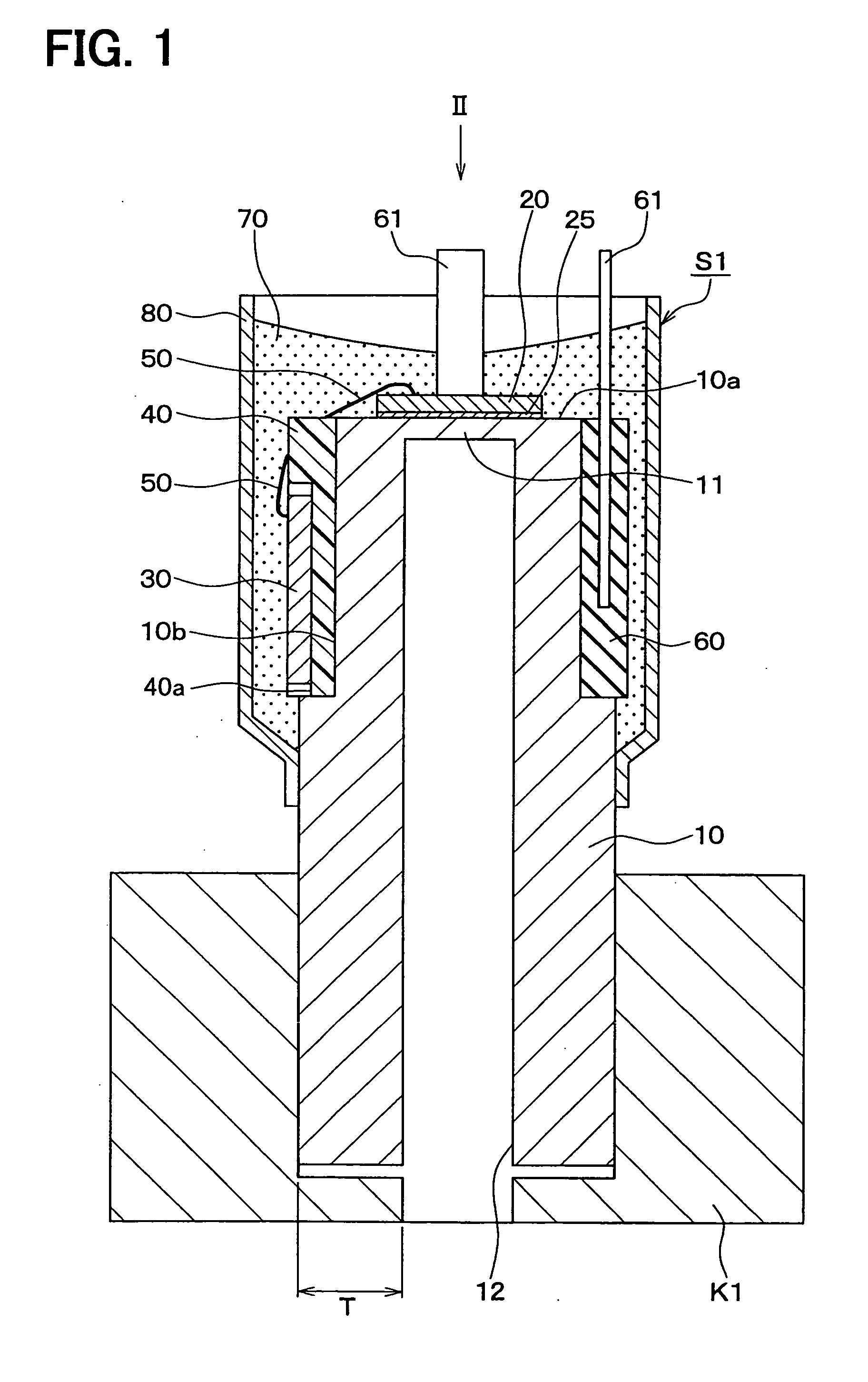
[0026] A preferred embodiment of the present invention will be described with reference to FIGS. 1-5. The present invention is applicable to sensors for detecting a physical amount such as a pressure, an acceleration or a gas density. FIGS. 1-5 show a pressure sensor as a preferred embodiment of the present invention. This pressure sensor can be used in an automobile vehicle for detecting a pressure of brake oil, a fuel pressure in a fuel pipe or the like. In FIG. 1, a pressure sensor S1 is hermetically connected to a structure K1 containing a pressure to be detected.

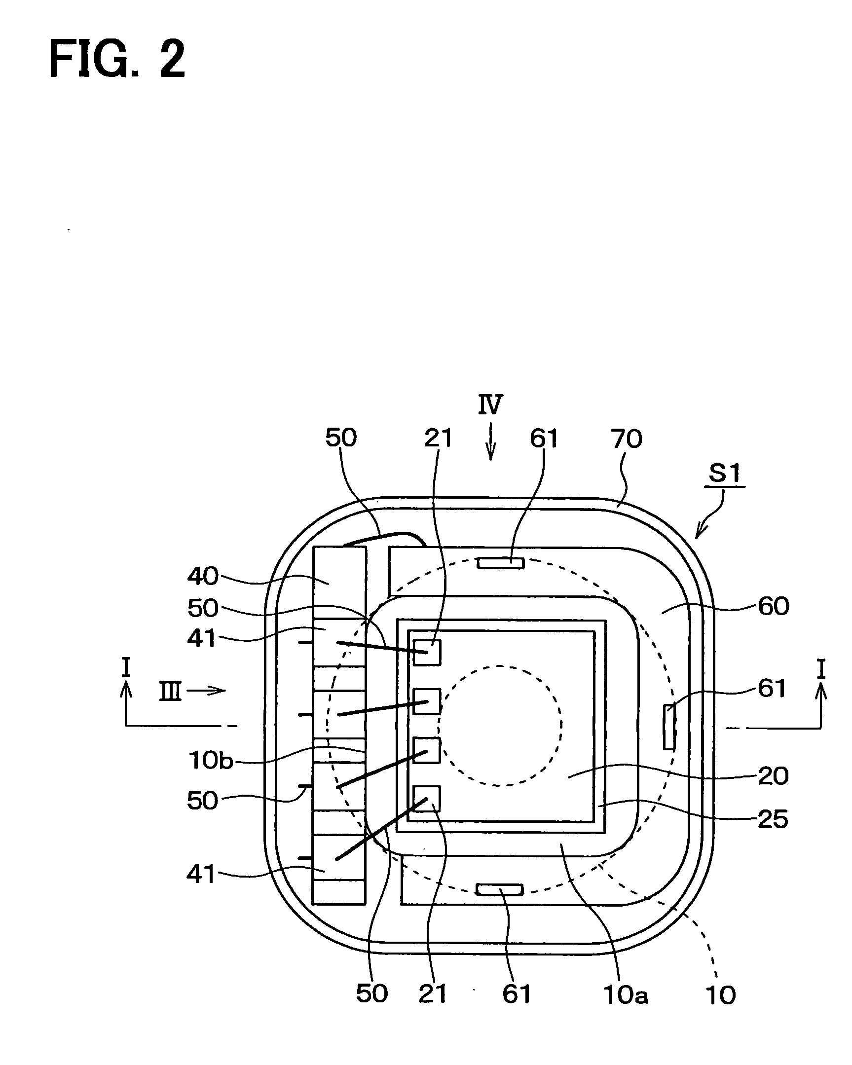
[0027] The pressure sensor S1, as shown in FIGS. 1-5, is composed of: a cylindrical stem 10 having a diaphragm 11 at one axial end and an opening 12 at the other axial end; a sensing member such as a semiconductor sensor chip 20 mounted on an outer surface 10a of the diaphragm 11; a circuit board 30 for processing sensor signals; and other associated components. The diaphragm 11 is made thin so that it distorts when a ...


PUM

PropertyMeasurementUnit
electricallyaaaaaaaaaa
pressureaaaaaaaaaa
electricalaaaaaaaaaa

Abstract

A pressure sensor for detecting a pressure such as a brake oil pressure in an automobile is composed of a cylindrical stem, a sensor chip and a circuit board for processing an electrical signal from the sensor chip. The cylindrical stem includes a thin diaphragm formed at an axial end and an opening formed at the other axial end. The sensor chip is mounted on the diaphragm, and the circuit board is mounted on a flat side surface formed on the outer periphery of the cylindrical stem so that the circuit board is positioned perpendicularly to the sensor chip, thereby reducing a size of the pressure sensor in the radial direction of the stem. The pressure to be detected is introduced into the cylindrical stem from its opening, and the pressure is detected by the sensor chip mounted on the diaphragm.

Description

CROSS-REFERENCE TO RELATED APPLICATION [0001] This application is based upon and claims benefit of priority of Japanese Patent Application No. 2003-383994 filed on Nov. 13, 2003, the content of which is incorporated herein by reference. BACKGROUND OF THE INVENTION [0002] 1. Field of the Invention [0003] The present invention relates to a sensor for detecting a physical amount, such as pressure or acceleration, and more particularly to a pressure sensor having a sensor chip and a circuit for processing sensor signals mounted on a cylindrical stem that includes a diaphragm. [0004] 2. Description of Related Art [0005] An example of this kind of pressure sensor is disclosed in JP-A-2001-272297. The pressure sensor is composed of a cylindrical stem having a diaphragm at one axial end. A pressure to be measured is introduced into the cylindrical stem from an opening formed at the other axial end of the stem, and the diaphragm distorts according to an amount of pressure applied thereto. A ...

Claims


Application Information

Patent Timeline
Patent Type & Authority Applications(United States)
IPC IPC(8): G01L9/02G01L9/00G01L9/04G01L19/04G01L19/14G01L23/24
CPCG01L9/0055G01L19/0627G01L19/148G01L19/147H01L2224/48091H01L2224/73265H01L2924/00014G01L19/14G01L9/04
Inventor IMAI, MASAHITOMURAKAMI, YOSHIFUMI
Owner DENSO CORP
Learn More