Check valve

a check valve and valve body technology, applied in the field of valves, can solve the problems of immobilizing the poppet within the valve, affecting the smooth and the likely lodgement of the interior seat of the conventional poppet valve, so as to prevent the lodging of the guide legs and facilitate the operation of the check valv

Inactive Publication Date: 2005-05-19
DANFOSS FLOMATIC CORPORTION
View PDF29 Cites 25 Cited by
  • Summary
  • Abstract
  • Description
  • Claims
  • Application Information

AI Technical Summary

Benefits of technology

[0007] A flow path for debris is formed between this recessed or cut back portion of the outer peripheral surface of each guide leg and the inner surface of the flange. This flow path provides for self cleaning of the valve by allowing debris to pass through the valve while preventing the lodging of the guide legs by debris in the valve aperture. The poppet valve moves around more with the recessed or cut back sections, which assist in shaking or cleaning out debris that, in the past, lodged between the guide legs and inner surface of the flange.
[0008] Additional advantages are provided through the provision of a check valve having a poppet valve with legs constructed in accordance with the principles of the present invention described and claimed herein by reducing the surface area in direct contact with the inner surface of the valve aperture. The check valve described and claimed herein assures smooth operation of the check valve by preventing the poppet valve from becoming lodged in the valve aperture by debris sticking the guide legs within the valve aperture defined by the flange.

Problems solved by technology

However, conventional poppet valves are likely to become lodged in the interior seat provided by an annular flange within the valve body by debris.
As a result, conventional poppet valves are stuck in an open position in the valve aperture, immobilizing the poppet within the valve.
When this happens, it is almost impossible to dislodge the poppet valve without dismantling the check valve.

Method used


Image

  • Check valve
  • Check valve
  • Check valve

Examples


Embodiment Construction

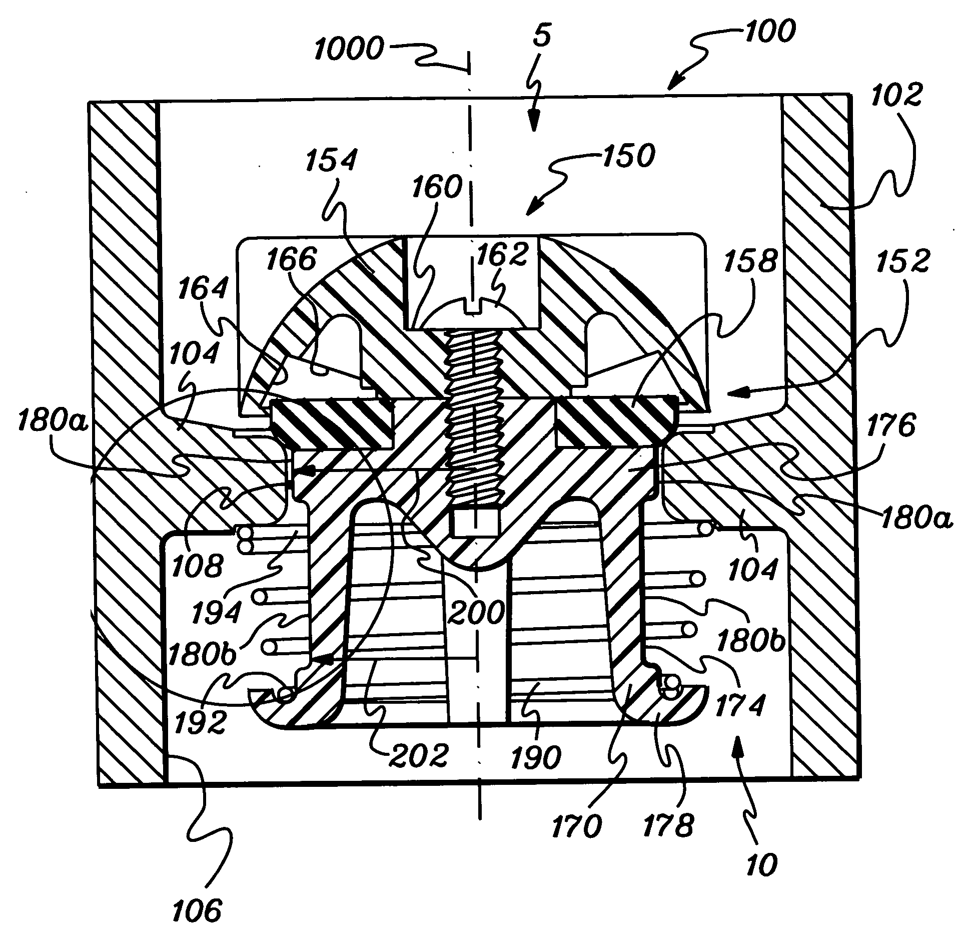
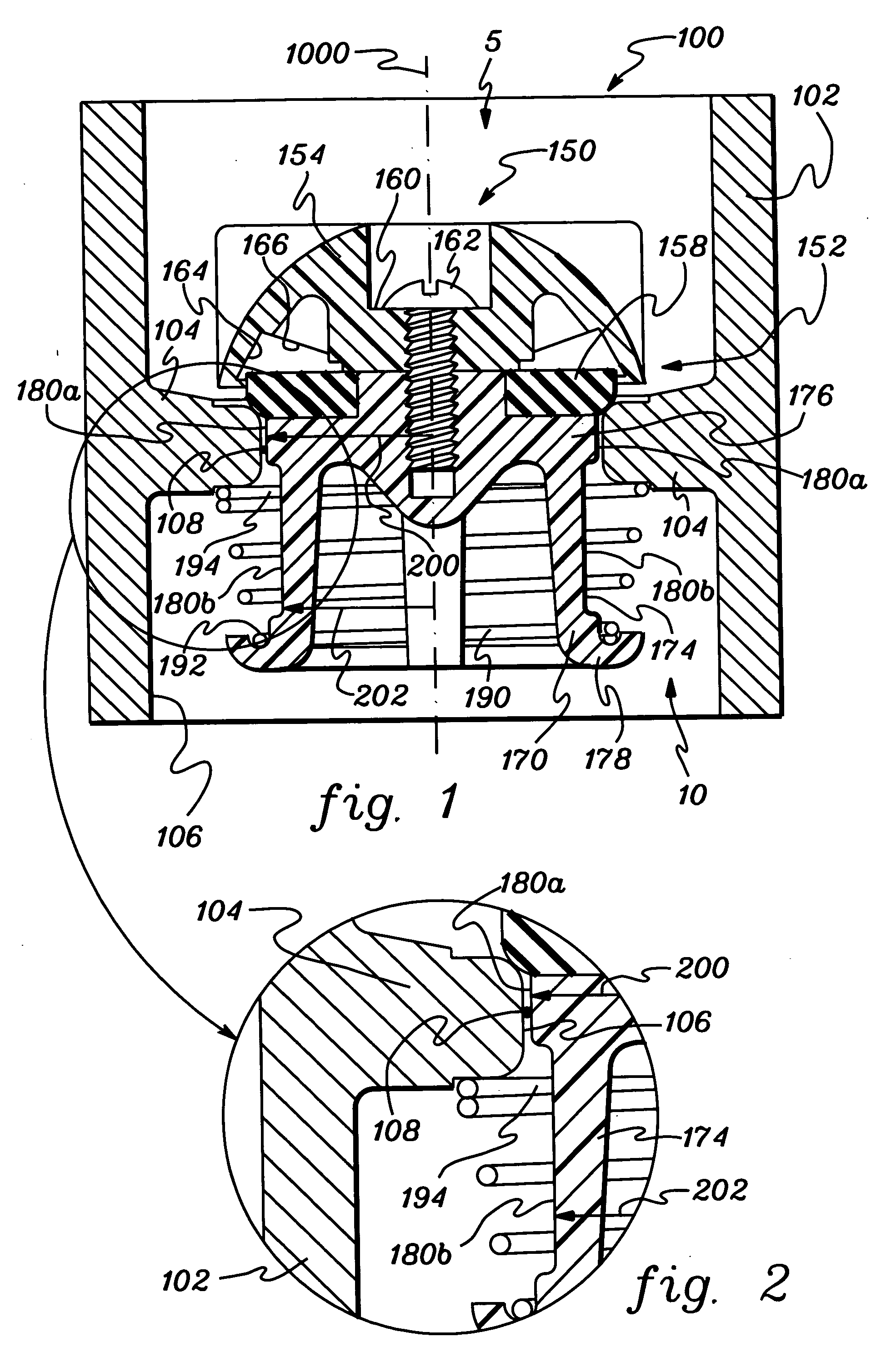
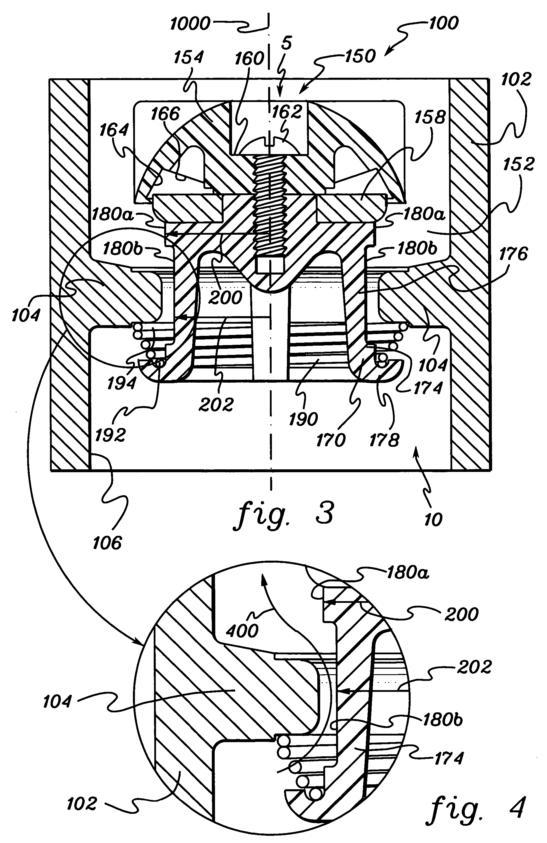
[0019] Presented herein is an improved check valve, which provides an enhanced poppet valve. The enhanced poppet valve includes legs having outer peripheral surfaces facing an inner surface of a flange forming a valve aperture. A section of the outer surface of each leg is recessed or cut back from the inner surface of the flange such that the radial distance of this section from the longitudinal axis of the poppet valve is less than the radial distance between the rest of the outer peripheral surface of the leg and the longitudinal axis. With this recessed section, a flow path is created to allow for debris to pass between the outer peripheral surface of each guide leg and the inner surface of the flange. The improved check valve assures smooth operation by preventing the poppet valve from becoming lodged within the check valve as debris, such as, for example, sand, passes through the valve while the valve is open.

[0020] Conventional check valves have a tubular valve casing and a ...


PUM


Abstract

A check valve comprises a casing having a flange extending circumferentially around the inner periphery of the body. The flange defines a valve aperture for receiving a poppet valve. The poppet valve includes a stem including a plurality of legs each having an outer peripheral surface facing the inner surface of the flange. The outer peripheral surface of the legs having a first section in close proximity to the inner surface of the flange and a second section recessed or cut back from the first section. The second section defines a flow path to allow debris to pass through the valve between the outer peripheral surface and the inner surface of the flange during operation.

Description

TECHNICAL FIELD [0001] This invention relates generally to valves, and more particularly, to a check valve with an improved design and construction. BACKGROUND OF THE INVENTION [0002] Check valves are designed to permit the flow of fluid in one direction while preventing the fluid from flowing in the reverse direction. Conventional check valves utilize a single poppet valve within a body, which controls the flow of fluid therethrough. [0003] Check valves are used for a number of applications, including the development of new wells containing heavy amounts of debris, e.g. sand suspended in water. As a new well is developed, water and debris are pumped out of the well by submerging a pump on the bottom of the well and directing the water and debris out through a valve mounted at or near the discharge of the pump. [0004] However, conventional poppet valves are likely to become lodged in the interior seat provided by an annular flange within the valve body by debris. As a result, conven...

Claims


Application Information

Patent Timeline
Patent Type & Authority Applications(United States)
IPC IPC(8): F16K15/02
CPCF16K15/026Y10T137/7931
Inventor MAGDA, MARK
Owner DANFOSS FLOMATIC CORPORTION
Why Eureka
Try Eureka