Universal lamp illumination system

a technology of universal lamps and illumination systems, applied in the direction of cathode-ray/electron beam tube circuit elements, lighting and heating apparatus, cathode device connections, etc., can solve the problems of unsuitable inability to provide en masse adoption of fluorescent lamps, and inability to directly interchange fluorescent lamps. to achieve the effect of reducing costs and increasing user-friendliness

Inactive Publication Date: 2005-05-19
BISHOP JAMES G
View PDF23 Cites 31 Cited by
  • Summary
  • Abstract
  • Description
  • Claims
  • Application Information

AI Technical Summary

Benefits of technology

[0010] Through use of the devices of this invention, the retrofitting of a wide variety of fluorescent lamps to existing incandescent lamp sockets is now possible for the first time, at a greatly reduced cost and a greatly increased degree of user-friendliness.

Problems solved by technology

However, the discharge lamps typically require an increased amount of associated hardware relative to incandescent lamps.
However, each of the teachings of the prior art are not without one or more inherent disadvantages rendering them unsuitable for providing en masse adoption of the use of fluorescent lamps in various capacities formerly reserved for incandescent lighting.
These fluorescent lamps are not directly interchangeable with the incandescent lamps they are intended to replace owing to the different operating requirements of each.
Built-in ballasts are common in fluorescent lamps for wattages up to about 20 W. However, such systems are uneconomical in that when the CFL lamp eventually fails the unit as a whole, including the ballast, must be discarded.
For the fluorescent lamps available which contain internal ballasts, the ability to include the ballast in the lamps is limited by the wattage of the lamp.
Furthermore, in general terms, the systems presently available possess the drawbacks that: 1) the increase in lamp wattages desired for a particular use are accompanied by a attendant increase in the size of the ballast required; and 2) many of the newer lamps are incompatible with 110-120 VAC house current and therefore require that special fixtures or lamp / ballast assemblies must be used.
Also, owing to the inherent design of the circuitry of the instant invention, it is not possible for a fluorescent lamp to operate in the situation where there is no ballast connected to the adapter.
However, with the two-pin compact fluorescent lamps a magnetic ballast must be used because the high voltage kick putout by the glo-bottle starter built into the lamp would destroy the electronics.
A higher lamp voltage must be supplied by the ballast which is the reason why these ballasts are larger, more expensive, and normally separate from the lamp.
While the prior art has attempted to permit the same, the devices therein taught are much too large or cumbersome to be used in such applications, since the prior art devices are not suited to fit within existing lamp-shade support harps.

Method used


Image

  • Universal lamp illumination system
  • Universal lamp illumination system
  • Universal lamp illumination system

Examples


Embodiment Construction

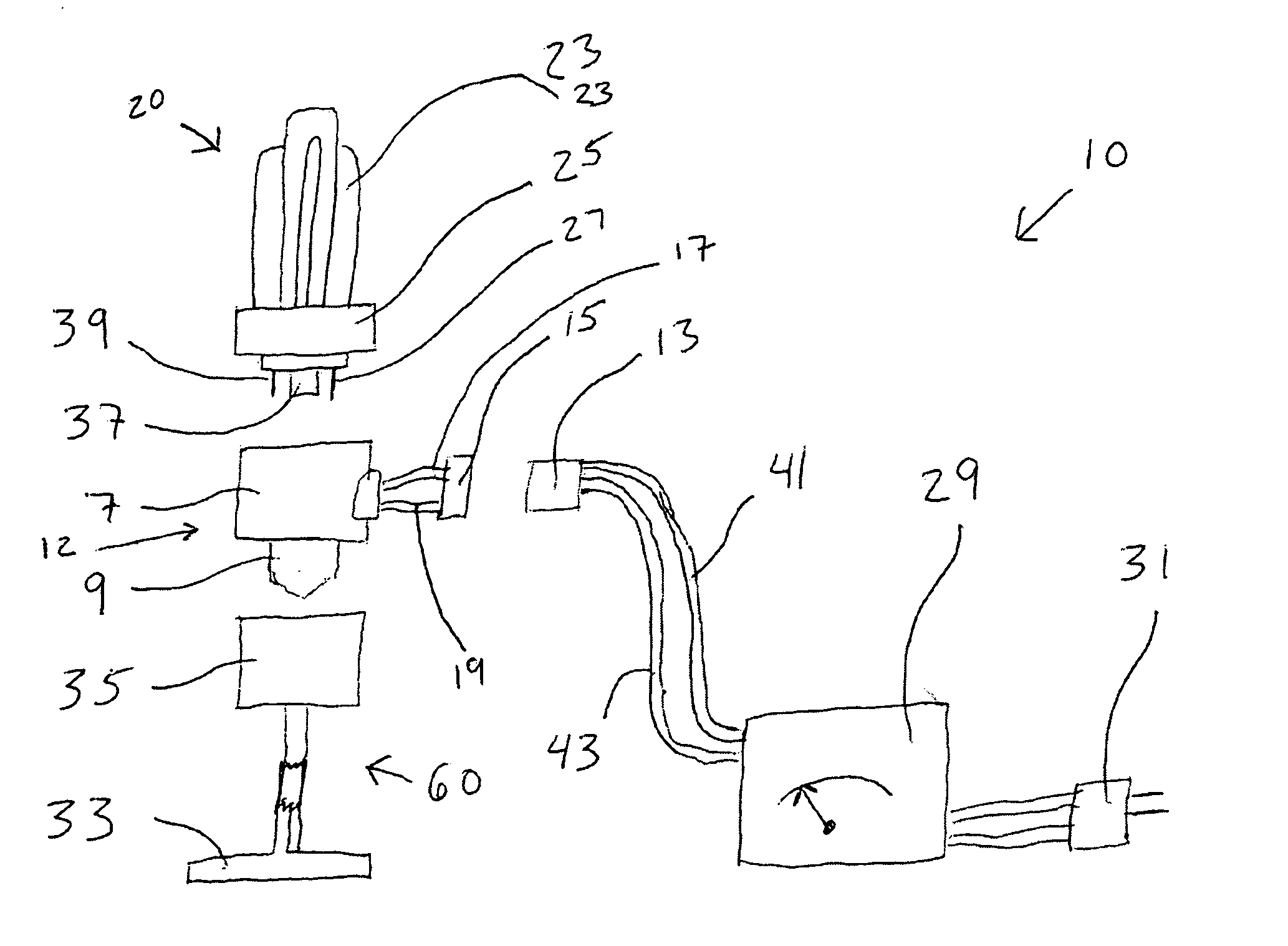
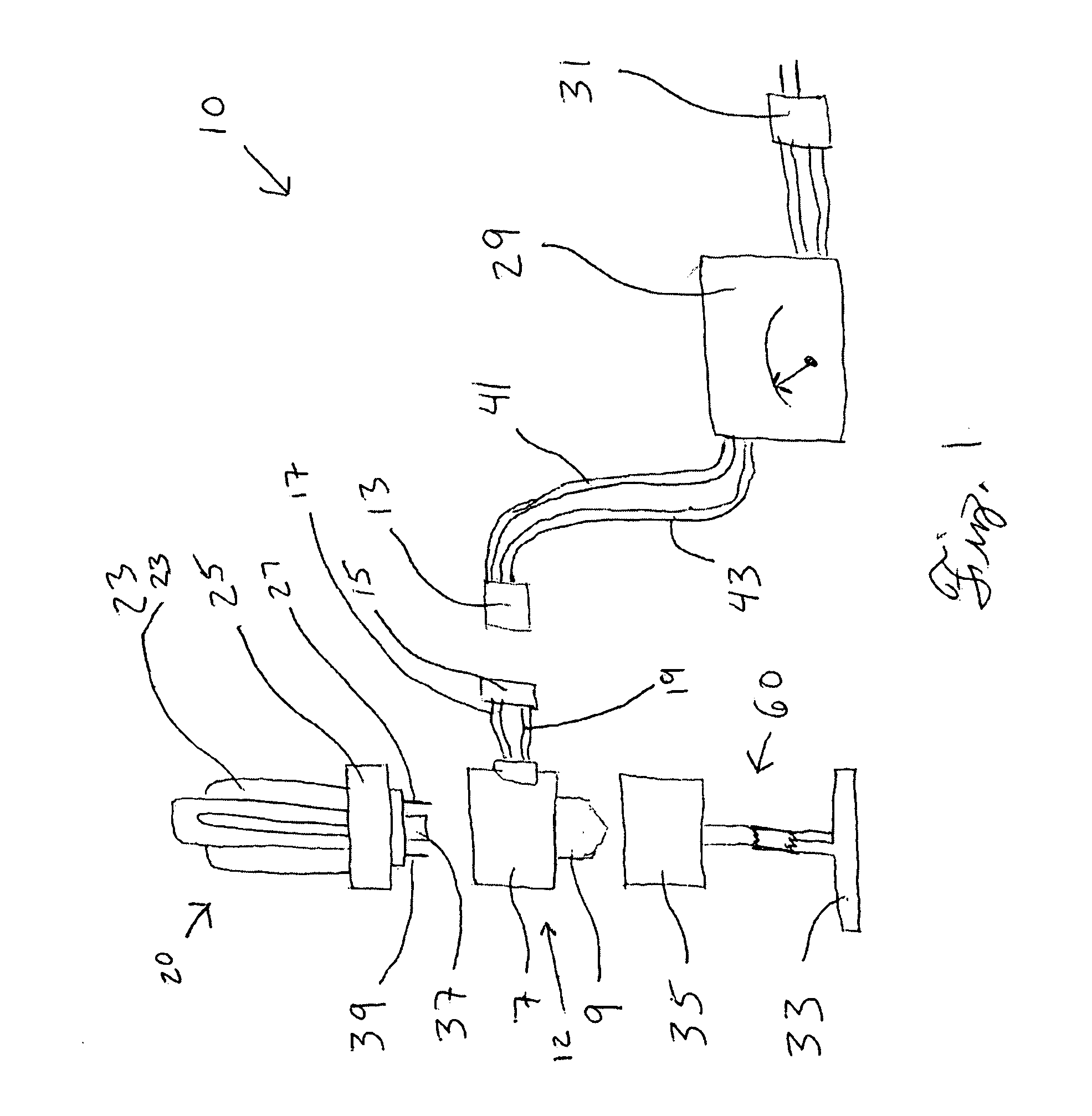
[0016] Referring to the drawings and initially to FIG. 1 there is shown an exploded schematic diagram of a system according to the present invention. In FIG. 1 there is shown an existing lamp 60, which comprises a base portion 33 and a socket portion 35 in this embodiment. However, the present invention is not limited to lamps having base portions; hence this embodiment shall not be construed as being delimitive of the metes and bounds of the invention. The socket portion 35 is a conventional light bulb socket, as is well-known in the art, into which may be screwed an ordinary light bulb.

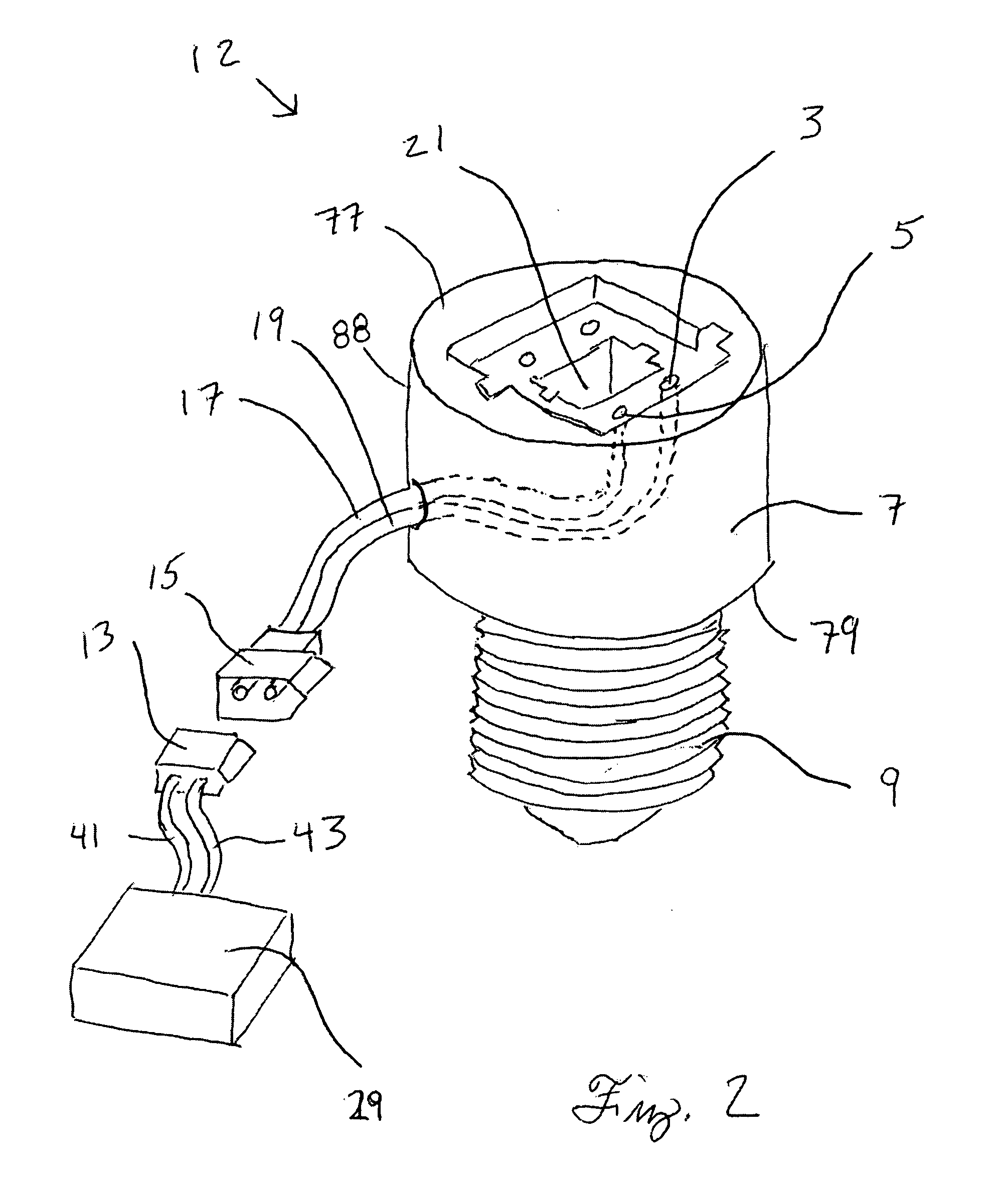
[0017] There is an adapter 12 according to the invention, which comprises a threaded tip portion 9 which is adapted to be screwed into the socket portion 35 in the same fashion as a light bulb would be screwed in. The threaded tip portion 9, however, is different than the threaded portions on the light bulbs of the prior art, in that it may be comprised of a non-conducting material, since the purpo...


PUM


Abstract

Adapters for retrofitting lamps which were originally designed to function with conventional incandescent light bulbs with arc-discharge lamps are provided. Use of an adapter according to the invention provides a system by which a lamp may employ an arc discharge lamp for illuminative purposes, which lamp does not receive its electrical energy through the threads of the socket on the lamp, as in conventional incandescent lighting, but rather receives its energy from a source external to the lamp. The original wiring which came with the lamp may be eliminated by use of a system according to the present invention.

Description

CROSS-REFERENCE TO RELATED APPLICATIONS [0001] This application claims the benefit of U.S. Provisional Application Ser. No. 60 / 519,955, filed Nov. 17, 2003, which application is incorporated herein by reference in its entirety.TECHNICAL FIELD [0002] The present invention relates generally to the field of electric illumination. More particularly it relates to means for retrofitting existing lamp fixtures to render them useful with fluorescent lamps. BACKGROUND INFORMATION [0003] Since the earliest of modem times, it has been recognized as desirable to provide a cost-effective means for producing useful, practical illumination from electrical energy. Most inhabitants of modem countries are familiar with various lighting means including incandescent lamps and arc discharge or fluorescent lighting. It is to the art of arc discharge lamps to which the present invention is concerned, to the extent that it is desirable to provide a cost-effective means for retrofitting existing electrical ...

Claims


Application Information

Patent Timeline
Patent Type & Authority Applications(United States)
IPC IPC(8): F21S6/00F21V23/02H01R33/94H05B41/02
CPCF21S6/00F21V23/02Y02B20/19H05B41/02H01R33/94Y02B20/00
Inventor BISHOP, JAMES G.
Owner BISHOP JAMES G
Why Eureka
Try Eureka