
Short circuit detector for shield conductor in a fieldbus network

a short circuit detector and shield conductor technology, applied in the field of fieldbus networks, can solve the problems of significant degrading of the performance of the network, relatively harmless common mode voltage, and problem of occurrence of problems

Inactive Publication Date: 2005-05-19
RELCOM INC AN OREGON
View PDF7 Cites 31 Cited by
  • Summary
  • Abstract
  • Description
  • Claims
  • Application Information

AI Technical Summary

Benefits of technology

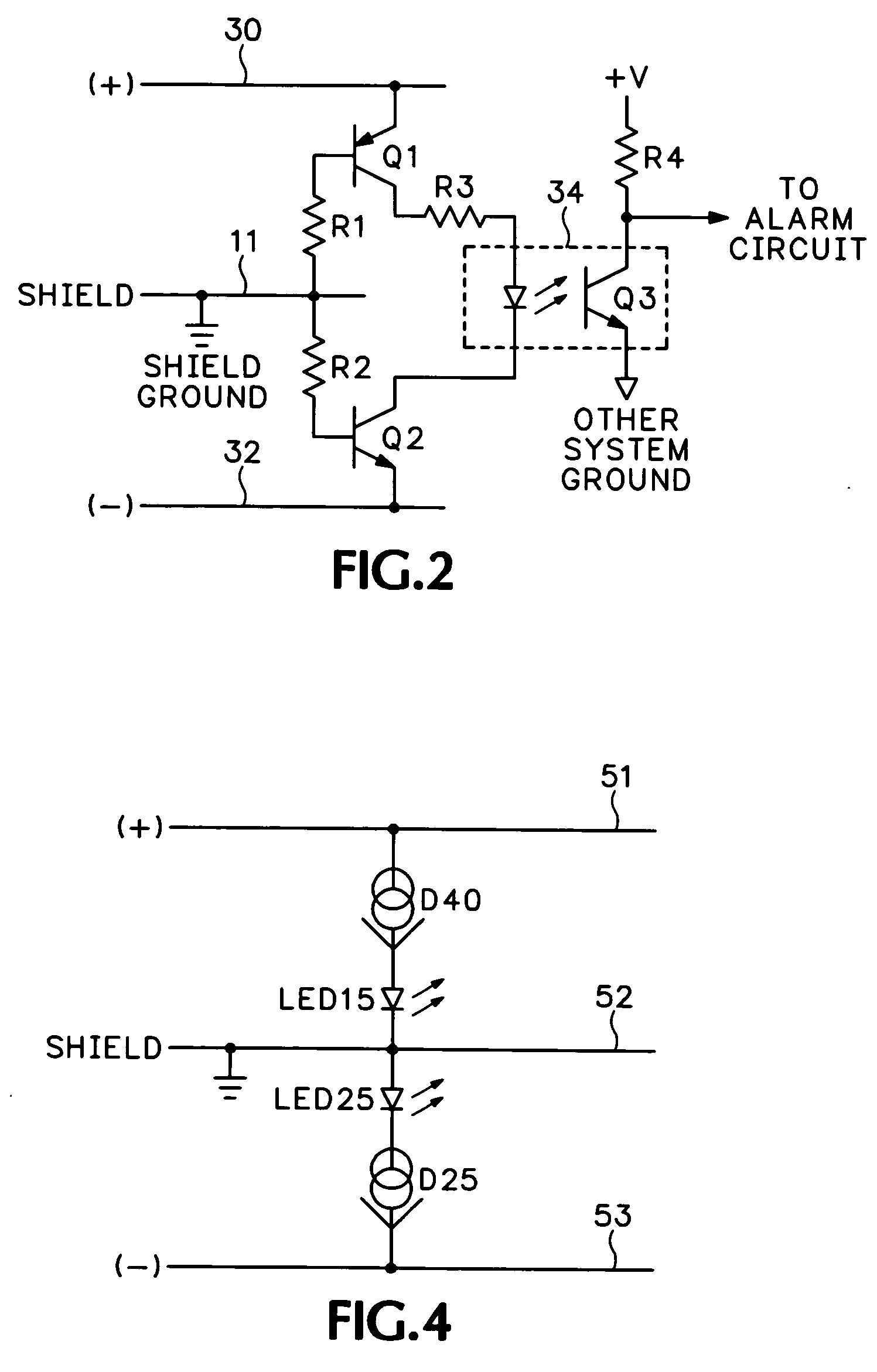
[0017]FIG. 2 is a schematic diagram of a preferred embodiment of the short circuit detector of the present invention.
[0018]FIG. 3 is a schematic ...

Problems solved by technology

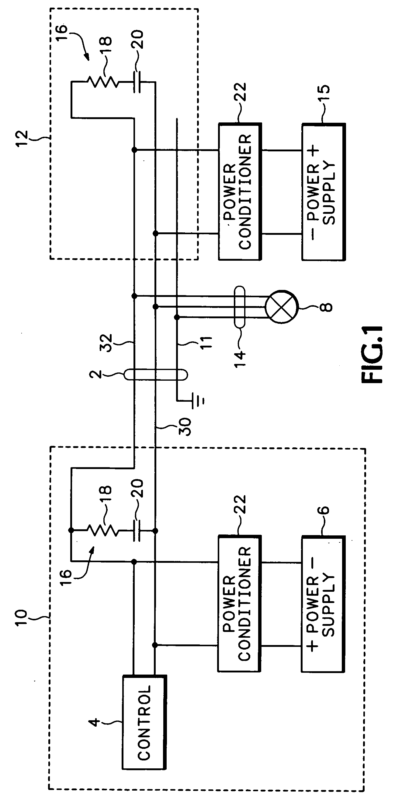
A problem can occur, however, if either of the two wires of the home run 2 are short-circuited to the shield 11.
If either of the two wires of the twisted pair becomes coupled to the shield 11 through improper cable installation, deterioration of the cable such as a tear or a cut, or workman's error, the performance of the network can be substantially degraded.
Common mode voltage is relatively harmless because receivers in the devices connected to the cable are designed to reject it.
If, however, one wire of the twisted pair becomes shorted to the shield, the two wires will no longer be balanced.
Noise voltage would then affect one wire more than the other and would produce a differential noise.
Differential noise is difficult, if not impossible, for receivers in the downstream devices to eliminate and therefore degrades the receiver's ability to detect signals correctly.
Secondly, a short between one of the cable wires and the shield can disable current limiting devices that are typically used between the trunk cable and the drop cable.
If they are not, a short circuit on the drop cable can bypass the protective current limiting circuit and cause the loss of power to the entire network.
Often when a failure occurs, its cause is not readily known.
This type of diagnostic work is costly and time-consuming.

Method used


Image

  • Short circuit detector for shield conductor in a fieldbus network
  • Short circuit detector for shield conductor in a fieldbus network
  • Short circuit detector for shield conductor in a fieldbus network

Examples


Embodiment Construction

[0020] Referring to FIG. 2, a fieldbus home run cable 2, when connected to a power supply such as power supply 6 of FIG. 1, includes a positive lead 30 and a negative lead 32. A shield conductor 11 is a grounded sleeve or jacket that encircles the positive and negative leads 30, 32. In a typical fieldbus installation, the positive and negative leads are connected to a twenty-four-volt power supply through a power conditioner (22). The positive lead 30 is connected to the emitter of transistor Q1. The base of Q1 is connected through a resistor R1 to the shield 11. Similarly, the negative lead 32 is connected to the emitter of transistor Q2 and the base of Q2 is connected to the shield 11 through resistor R2. The collector of Q1 is coupled through a resistor R3 to the light-emitting diode (“LED”) of an opto-isolator isolator 34. The output of the LED in the opto-isolator 34 is connected to the collector of Q2.

[0021] The isolated side of the opto-isolator 34 comprises a photosensitive...


PUM


Abstract

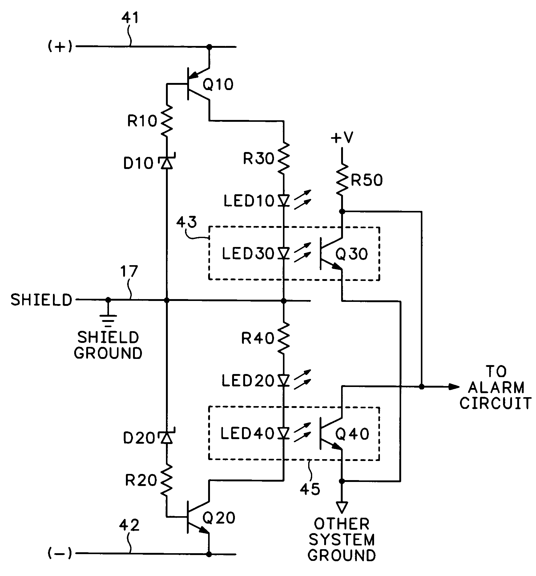
A short circuit detector for a fieldbus network which includes power / data wires that are typically positive and negative, respectively, and a shield conductor connected to a ground includes first and second high-impedance semiconductor circuits coupled between each of the leads and the shield conductors. Both circuits may either have a dedicated alarm indicator which indicates the presence of a short circuit between that conductor and the shield and / or may be coupled together to an alarm circuit which activates an alarm whenever a short circuit exists between either of the power / data leads and the shield conductor. The alarm circuit may have a ground which is isolated from the shield ground and may thus employ an isolation device such as an opto-isolator.

Description

CROSS-REFERENCE TO RELATED APPLICATIONS [0001] Not Applicable. STATEMENT REGARDING FEDERALLY SPONSORED RESEARCH OR DEVELOPMENT [0002] Not Applicable. REFERENCE TO SEQUENCE LISTING, A TABLE, OR A COMPUTER PROGRAM LISTING COMPACT DISK APPENDIX [0003] Not Applicable. BACKGROUND OF THE INVENTION [0004] The present invention relates to a fieldbus network and, more particularly, to a short circuit detector to protect a fieldbus network from an electrical short between the network's power / data wires and a shield connection. [0005] In a typical industrial plant application, sensors measure position, motion, pressure, temperature, flow, and other parameters related to the operation of process machinery and activities. Actuators, such as valves and motor controllers, control the operation of the machinery and process activities. The sensors and actuators are remotely located from the human and computerized controllers which gather information from the sensors and direct operation of the actua...

Claims


Application Information

Patent Timeline
IPC IPC(8): G01R31/02G08B21/00H04B3/46H04B3/54
CPCG01R31/025H04B3/46H04B3/548H04B2203/5495H04B2203/5458H04B2203/547H04B2203/5483H04B2203/5425G01R31/52
Inventor GRAUBE, MARIS
Owner RELCOM INC AN OREGON
Learn More