Antenna element, loop antenna using the antenna element, and communications control apparatus using the antenna for wireless communications medium

Inactive Publication Date: 2005-05-19
PANASONIC CORP
View PDF9 Cites 20 Cited by
  • Summary
  • Abstract
  • Description
  • Claims
  • Application Information

AI Technical Summary

Benefits of technology

[0026] Furthermore, the antenna element may be composed by disposing a conductive comblike object on a conductor surface by way of an insulator. Accordingly, electromagnetic interaction is decreased between the magnetic near field of electromagnetic waves radiated from the conductor of the antenna element and the branch of the conductive comblike object, and the eddy current generated in the conductive comblike object is smaller, and attenuation of magnetic near field is suppressed. Further, since the conductive comblike object is the ground potential, the electric far field is attenuated. Still more, necessary members of branches are fewer than in bag shape or lattice shape, and insulation at intersection of branches is not necessary.
[0027] Also in this antenna element, the conductor extending direction may be formed to intersect with the disposing direction of the comb tooth portion in the conductive comblike object. As a result, fluctuations of layout of comb tooth portions for composing the conductive comblike object disposed on the conductor surface are further decreased, and fluctuations are reduced in the individual positions of the antenna element about the attenuation suppressing effect of magnetic near field and attenuation effect of electric far field. Preferably if the conductor extending direc

Problems solved by technology

The intensity of radio frequency electric field is regulated under law, and to conform to regulation, for example, it is attempted to lower the output of antenna, but communication distance is shortened and other problems

Method used


Image

  • Antenna element, loop antenna using the antenna element, and communications control apparatus using the antenna for wireless communications medium
  • Antenna element, loop antenna using the antenna element, and communications control apparatus using the antenna for wireless communications medium
  • Antenna element, loop antenna using the antenna element, and communications control apparatus using the antenna for wireless communications medium

Examples


embodiment 1

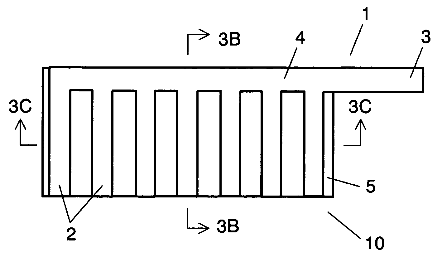
[0082]FIG. 1 is a perspective view of conductive electromagnetic shield in embodiment 1.

[0083] As shown in FIG. 1, conductive electromagnetic shield 1 comprises plural branches 2, ground contact 3 for grounding plural branches 2, and lead portion 4 for connecting plural branches 2 and ground contact 3.

[0084] Conductive electromagnetic shield 1 is comblike, and lead portion 4 having ground contact 3 at terminal end forms a comb spine portion, and plural branches 2 extended therefrom compose comb tooth portions.

[0085] Plural branches 2 are electrically connected to lead portion 4 having ground contact 3 at terminal end in each position. From an electrical point of view, it means that the route from a certain point on branches 2 to ground contact 3 along above branches 2 is determined uniquely. In other words, plural branches 2 are connected to ground contact 3 by way of lead portion 4 by such electric connection as to form an open loop.

[0086] In embodiment 1, comblike conductive e...

embodiment 2

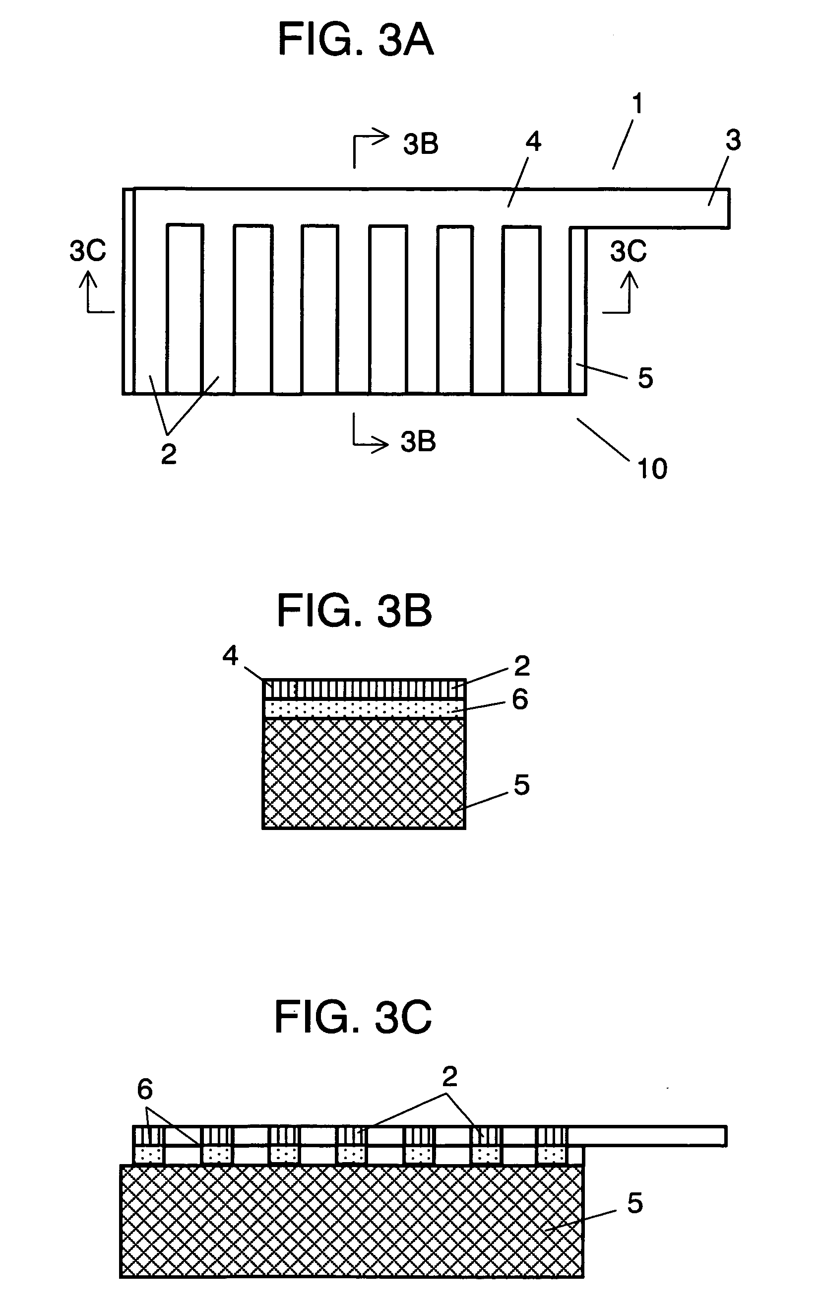
[0104]FIG. 4A is a plan view of antenna element in embodiment 2. FIG. 4B is a sectional view of 4B-4B in FIG. 4A. FIG. 4C is a sectional view of 4C-4C in FIG. 4A.

[0105] As shown in FIG. 4A, antenna element 10 has comblike conductive electromagnetic shield 1 disposed on the surface of conductor 5. Comblike conductive electromagnetic shield 1 is disposed on the surface of conductor 5 so that the extending direction of conductor 5 may be substantially orthogonal to the disposing direction of plural branches 2 corresponding to comb tooth portions of comblike conductive electromagnetic shield 1. Herein, the function of conductive electromagnetic shield 1 is same as in embodiment 1. If the surface of conductor 5 is a curved surface, or the shape of conductor 5 has curved line or curved point, at such curved surface, curved line or curved point, the extending direction of conductor 5 and the disposing direction of comb tooth portions of comblike conductive electromagnetic shield 1, that i...

embodiment 3

[0108]FIG. 5A is a plan view of antenna element in embodiment 3. FIG. 5B is a sectional view of 5B-5B in FIG. 5A. FIG. 5C is a sectional view of 5C-5C in FIG. 5A.

[0109] As shown in FIG. 5A, antenna element 10 has comblike conductive electromagnetic shield 1 disposed on the surface of conductor S. Comblike conductive electromagnetic shield 1 is disposed on the surface of conductor 5 so that the extending direction of conductor 5 may be substantially orthogonal to the disposing direction of plural branches 2 corresponding to comb tooth portions of comblike conductive electromagnetic shield 1. Herein, the function of conductive electromagnetic shield 1 is same as in embodiment 1. If the surface of conductor 5 is a curved surface, or the shape of conductor 5 has curved line or curved point, at such curved surface, curved line or curved point, the extending direction of conductor 5 and the disposing direction of comb tooth portions of comblike conductive electromagnetic shield 1, that i...


PUM


Abstract

The invention presents an antenna element capable of attenuating electric far filed while suppressing attenuation of magnetic near field of electromagnetic field radiated from loop antenna as an application example of antenna element, and a loop antenna and a communication control apparatus of wireless communications medium using the same. The antenna element of the invention comprises a conductor, and a conductive electromagnetic shield disposed on its surface by way of an insulator. The conductive electromagnetic shield has a ground contact, a lead portion, and a plurality of branches, and it is composed so as to determine uniquely the route from an arbitrary point of branches to the ground contact by way of the lead portion.

Description

BACKGROUND OF THE INVENTION [0001] 1. Field of the Invention [0002] The present invention relates to an antenna element for supplying electric power and transmission data to wireless communications medium such as contactless IC card, and acquiring reception data from the wireless communications medium, a loop antenna using such antenna element, and a wireless communication control apparatus using such loop antenna. [0003] 2. Background Art [0004] Hitherto, a radio-frequency identification (RF-ID) system has been known, which is designed to communicate with a wireless communications medium (such as contactless IC card) having an antenna coil without making contact, by making use of electromagnetic induction in an apparatus utilizing radio frequency electromagnetic field. [0005] In this system, a radio frequency magnetic field is used in communications, but the radio frequency electric field is generated simultaneously with the radio frequency magnetic field. The intensity of radio fr...

Claims


Application Information

Patent Timeline
IPC IPC(8): H01Q1/24H01Q9/30H01Q1/38H01Q1/52H01Q7/00H01Q7/04
CPCH01Q1/38H01Q7/04H01Q7/00H01Q1/52H01Q1/24H01Q1/526
Inventor NOTOHARA, YASUHIROKANEKO, SHINICHIROSHIMIZU, SHOICHIYOSHIDA, KOJI
Owner PANASONIC CORP
Why Eureka
Try Eureka