Communications system and method

a communication system and communication method technology, applied in the field of communication systems, can solve the problems of handheld devices being unable to experience problems processing a large volume of data transmitted by stationary terminals, the processing power of mobile telephones, pdas, etc., and achieve the effect of smooth communication and reducing the transmission of unnecessary data

Inactive Publication Date: 2005-05-19
HITACHI LTD
View PDF7 Cites 43 Cited by
  • Summary
  • Abstract
  • Description
  • Claims
  • Application Information

AI Technical Summary

Benefits of technology

[0017] According to the present embodiments, when two or more terminals each having a different number of vertical and / or horizontal dots that defines an output screen of one another's display device transmit / receive static image data or dynamic image data to / from one another, it is possible to reduce the transmission of unnecessary data and realize smooth communication.

Problems solved by technology

There is also the problem that even when a technology for compressing static image data or dynamic image data is used to standards such as JPEG or MPEG, it may be difficult to transmit desired image data.
In addition, mobile telephone, PDAs, and other hand-held terminals have relatively low processing power compared to stationary terminals, e.g., personal computers (PCs).
Accordingly, handheld devices are generally unable to experience problem processing a large volume of data transmitted by stationary terminals.
However,in the method according to the conventional technology described in JP Laid-open No. 10-51773, the radio-frequency components of the image are suppressed when the network becomes congested in terms of traffic.
The method using the conventional technology, therefore, is problematic if a specific section of an image is not displayed due to the traffic bottleneck.
When, as described above, a communication is to be conducted in real time between the terminals connected via a wireless network, it may be difficult to communication smoothly unless the display method to be used is changed according to communication conditions or display parameters.

Method used


Image

  • Communications system and method
  • Communications system and method
  • Communications system and method

Examples


Embodiment Construction

[0043] An embodiment of a communication system according to the present invention will be described in detail below with reference to the accompanying drawings.

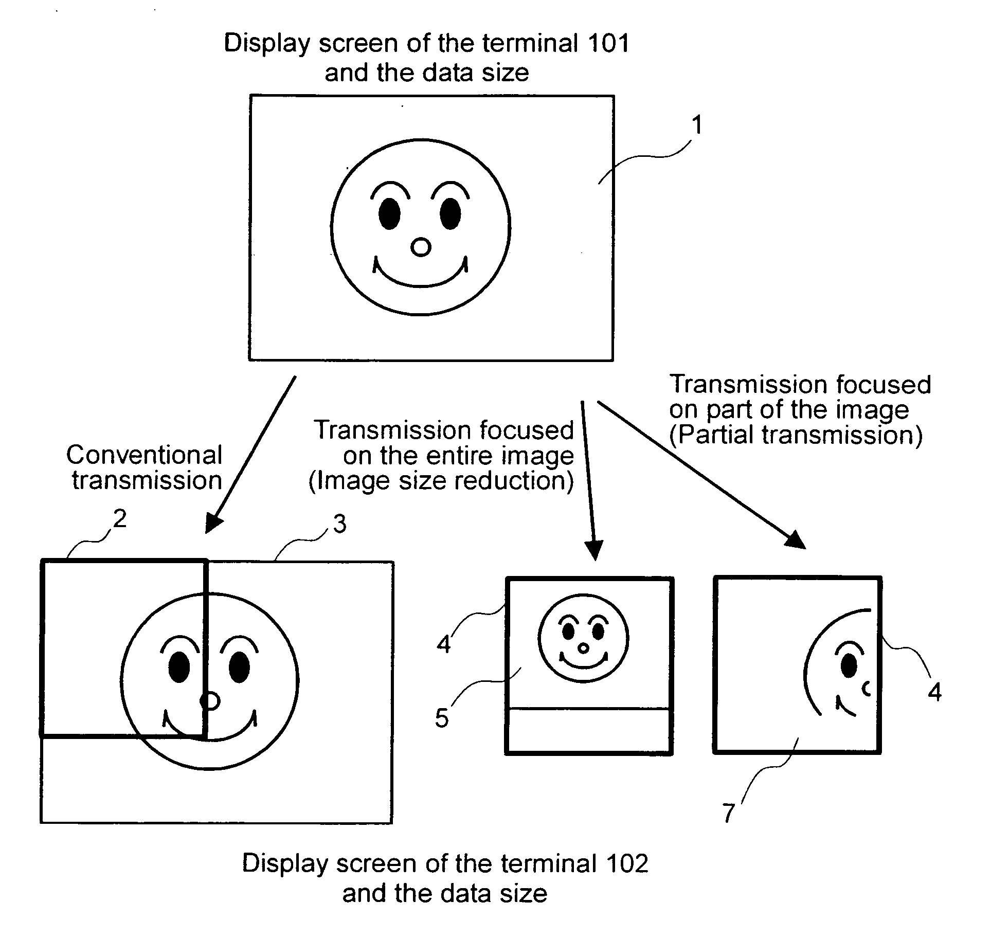
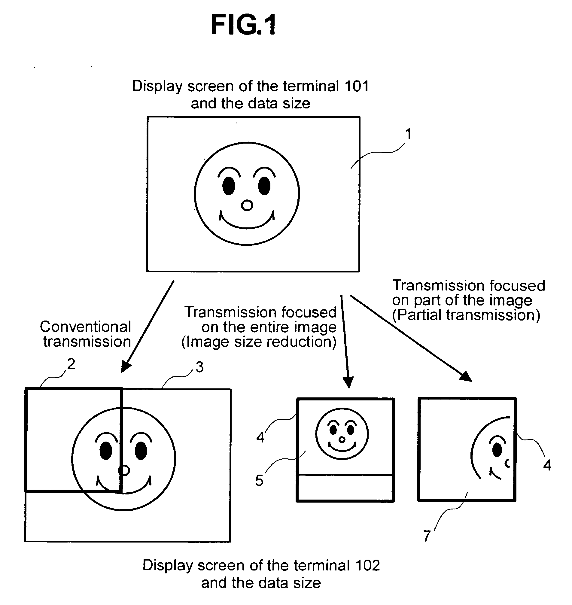
[0044]FIG. 1 is a diagram explaining the outline of image reduction / extraction according to an embodiment of the present invention.

[0045] In FIG. 1, image data 1 shown in an upper row is an example of the image data displayed on a display of a terminal 101 which to operate as a transmitting terminal. It is to be assumed that the size of a frame of the image data 1 indicates that size or resolution of the display device of the transmitting terminal 101 (i.e., the number of vertical and / or horizontal display dot / pixels). Is is to be assumed that a user of the terminal 101 transmits all or part of the image data 1 to a terminal 102 (receiving terminal) equipped with a display device having a display region 2 of the size (i.e., the number of vertical and / or horizontal display dots) shown as a thick line in a lower row, at the l...


PUM


Abstract

A communication terminal includes a display device configured to display an image on the display device according to image display parameters; a processor to process the images data; and a communication interface to transmit or receive data, the communication interface configured to be coupled to a remote image processing device via a network. Unnecessary data is prevented from being transmitted, and it becomes possible to reduce processing loads on the terminals to thereby display only the focused image data section in a shared fashion between the terminals during the communication. When a communication is conducted in real time, it can be explicitly indicated on what section of image data a user of a terminal which is to transmit the image data and a user of a terminal which is to receive the image data are to focus each other's attention during the communication.

Description

CROSS-REFERENCE TO RELATED APPLICATIONS [0001] The present application claims priority to Japanese Patent Application No. 2003-355359, filed on Oct. 15, 2003.BACKGROUND OF THE INVENTION [0002] The present invention relates to a communication system, and more particularly, to a communication system used and suitable for transmitting / receiving static image data and / or dynamic image data. [0003] In general, when voice data, hand-written data, and / or image data is to be exchanged between terminals during communication using a wireless network, to ensure effective use of a limited communication band of the network, the amount of data to be transmitted is reduced by applying a technology for compressing static image data / dynamic image data, such as JPEG or MPEG. Also, the technology described in, for example, JP10-51773, and in other documents, is known as a conventional technology relating to a method of transmitting / receiving dynamic image data smoothly between terminals by using the li...

Claims


Application Information

Patent Timeline
Patent Type & Authority Applications(United States)
IPC IPC(8): G06F3/14G06F13/00G09G5/02H04N1/00H04N1/333H04N7/14
CPCG06F3/1454G09G2340/0407G09G2340/14G09G2370/042H04N2201/33321H04N1/00307H04N1/33315H04N1/33376H04N2201/0096H04N1/00204
Inventor OKAMURA, SHINICHIROHIROI, KAZUSHIGETOMOKANE, TAKEO
Owner HITACHI LTD
Why Eureka
Try Eureka