Method and apparatus for determining a color and brightness of an LED in a printed circuit board

a technology of printed circuit board and color, applied in the direction of optical radiation measurement, instruments, spectrometry/spectrophotometry/monochromators, etc., can solve the problems of bulky, expensive fiber optics, and the inability to construct test fixtures, so as to eliminate the time-consuming and costly procedures. , the effect of reducing the cos

Active Publication Date: 2005-05-19
FINN TEST ELECTRONICS LLC
View PDF11 Cites 7 Cited by
  • Summary
  • Abstract
  • Description
  • Claims
  • Application Information

AI Technical Summary

Benefits of technology

[0007] A method and apparatus for determination of a color and brightness of an LED according to a preferred embodiment of this invention eliminates much of the time-consuming and costly procedures required by manual determination and the equally costly test fixtures requiring time-intensive and complex set-up and calibration.
[0013] It is one object of this invention to provide a method and apparatus for accurately and inexpensively determining a color and brightness of an LED.
[0015] It is another object of this invention to provide a method and apparatus for determining a color and brightness of an LED in a printed circuit board without requiring advance calibration.
[0017] It is still another object of this invention to provide a method and apparatus for determining a color and brightness of an LED that does not require placement of optical cables.

Problems solved by technology

Alternatively, a test fixture may be constructed including bulky and expensive fiber optics that extend between the printed circuit board to be tested and a test system.

Method used


Image

  • Method and apparatus for determining a color and brightness of an LED in a printed circuit board
  • Method and apparatus for determining a color and brightness of an LED in a printed circuit board
  • Method and apparatus for determining a color and brightness of an LED in a printed circuit board

Examples


Embodiment Construction

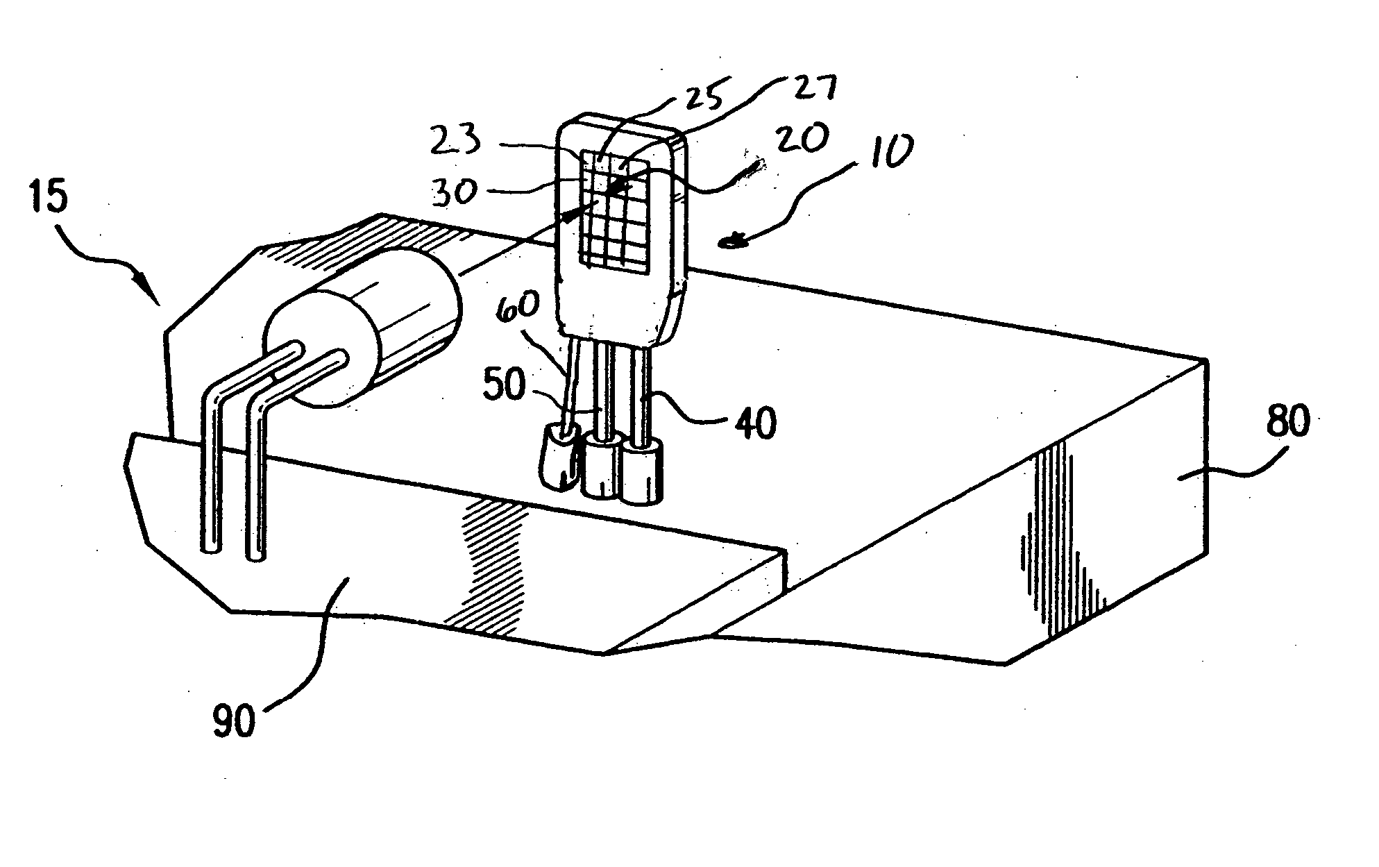
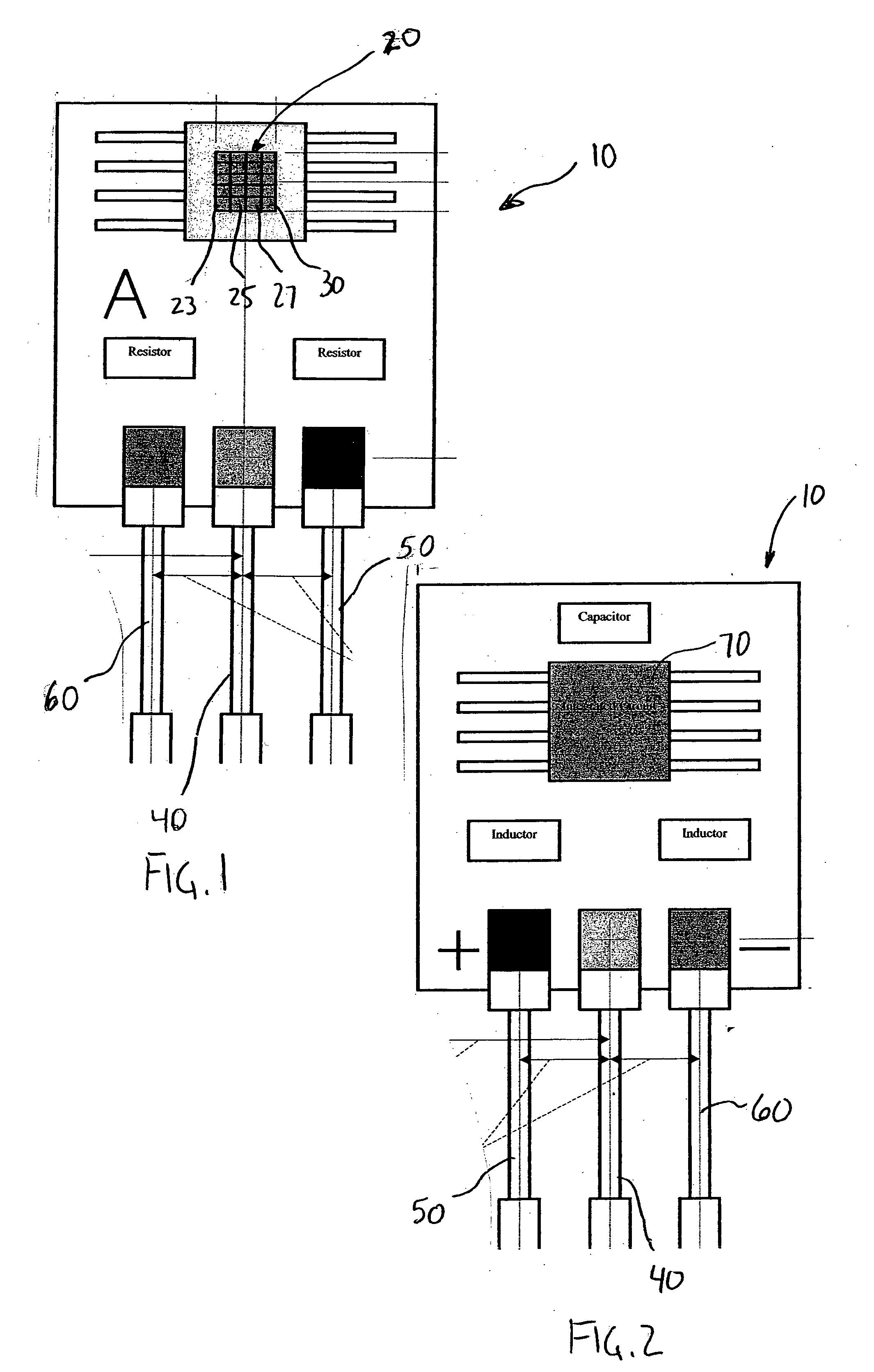
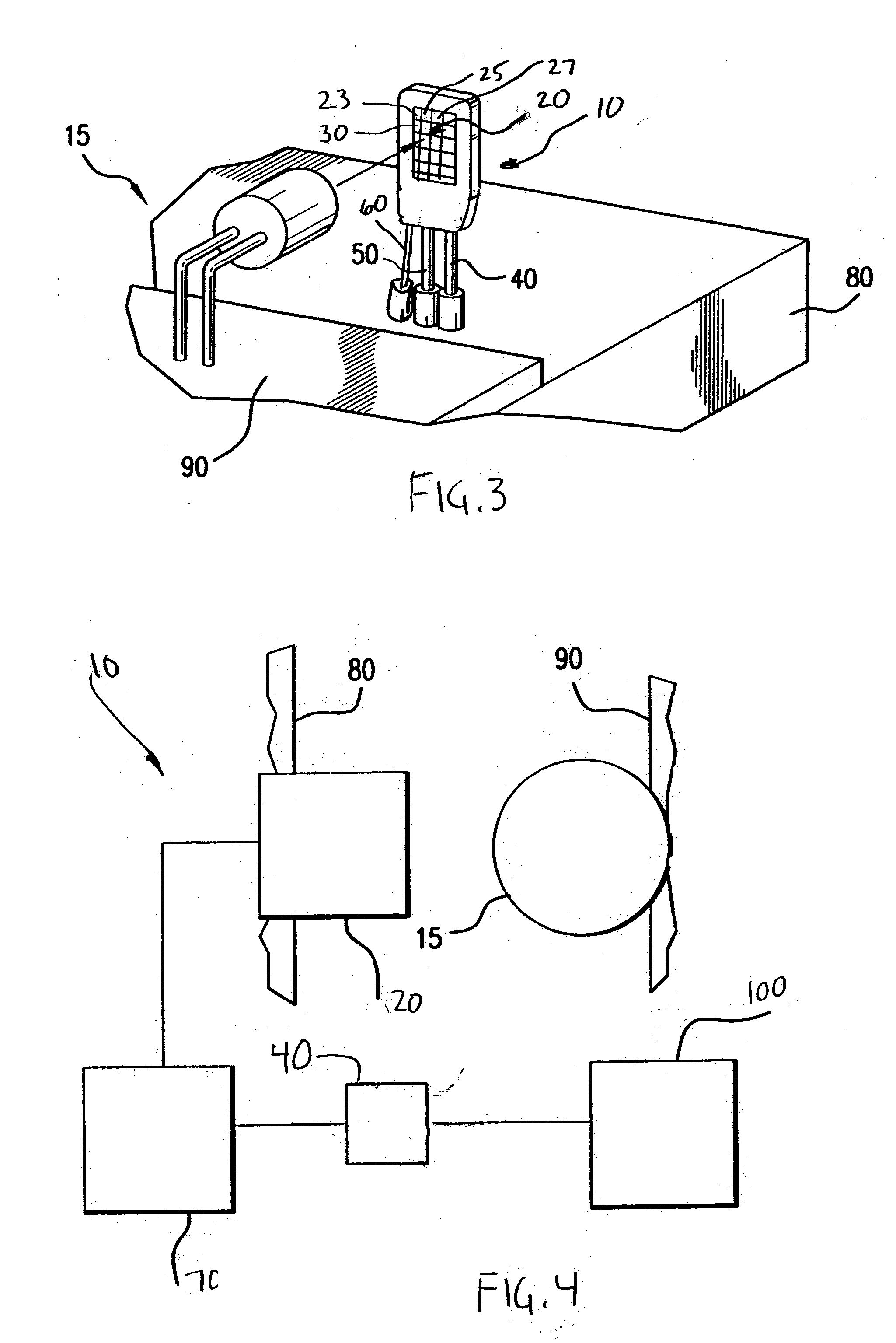
[0024] According to one preferred embodiment of this invention, an apparatus and system for determining a color and brightness of LED 15 in printed circuit board 90 is shown in FIGS. 1-4. LEDs 15 are typically used in printed circuit boards 90 and require verification and determination of their operation in a different manner than the traditional manner of verification of the placement and operation of integrated circuits within printed circuit board 90. LEDs 15 are available in clear / white and several common colors such as red, green and blue. Beyond mere verification of the operation of LED 15, it is also preferable, and an object of this invention, to determine the color and brightness of LED 15, in part to confirm that such LED is in the desired position in printed circuit board 90 and functions as intended.

[0025] The apparatus according to a preferred embodiment of this invention includes sensor 10. As described in more detail below, sensor 10 comprises an assembly of componen...


PUM


Abstract

A method and apparatus for determining a color and brightness of an LED includes a sensor having a plurality of filters arranged in a matrix and an output probe connected to the sensor, the output probe providing a color output and a brightness output in a single signal. The sensor may further include an input probe connected to the sensor providing power and a ground probe connected to the sensor providing a grounded connection to the sensor. The plurality of filters in the sensor are preferably configured in a matrix array of color receptors having different colors.

Description

BACKGROUND OF THE INVENTION [0001] 1. Field of the Invention [0002] This invention relates to a method and apparatus for verifying a color of an LED in a printed circuit board. [0003] 2. Description of Related Art [0004] Printed circuit boards often contain one or more light emitting diodes (LEDs) used as external signals, internal diagnostics and for other suitable applications. Typically, verification of the operation of a printed circuit board having LEDs required powering up a fully rendered printed circuit board and manually verifying the operation of the LEDs. Alternatively, a test fixture may be constructed including bulky and expensive fiber optics that extend between the printed circuit board to be tested and a test system. [0005] Alternatively, verification of the operation of LEDs within a printed circuit board may be accomplished without a power supply such as described in U.S. Pat. No. 6,490,037, issued to Schmitt, which is hereby incorporated by reference in its entire...

Claims


Application Information

Patent Timeline
Patent Type & Authority Applications(United States)
IPC IPC(8): G01J1/42
CPCG01J1/0488G01J2001/4252G01J3/513G01J1/42
Inventor SCHMITT, KEVIN
Owner FINN TEST ELECTRONICS LLC
Why Eureka
Try Eureka