Method and apparatus for determining presence and operation of a component in a printed circuit board

a technology of printed circuit board and component, which is applied in the direction of optical radiation measurement, instruments, spectrophotometry/monochromators, etc., can solve the problems of bulky, expensive fiber optics, and the construction of test fixtures, so as to eliminate the time-consuming and costly procedures. , the effect of reducing the number of times

Active Publication Date: 2019-05-28
NASA SOLUTIONS LLC
View PDF36 Cites 2 Cited by
  • Summary
  • Abstract
  • Description
  • Claims
  • Application Information

AI Technical Summary

Benefits of technology

[0008]A method and apparatus for determination of presence, brightness and / or color of a light emitting diode (LED) in a printed circuit board according to a preferred embodiment of this invention eliminates much of the time-consuming and costly procedures required by manual determination and the equally costly test fixtures requiring time-intensive and complex set-up and calibration.
[0009]The method and apparatus of this invention allows for testing for the presence, brightness and / or color of an LED in a printed circuit board, where the LED is biased with a constant current or with a current pulse while avoiding the time-consuming and costly procedures of previously known methods.
[0012]The apparatus of this invention preferably includes an oscillator connected to a processor. Preferably, the oscillator comprises an external oscillator that is used to acquire fast speed, higher accuracy and response times allowing the apparatus of this invention to take samples quicker than previously known sensor. Allowing the apparatus of this invention to take samples even when an LED or another component is biased with a current pulse. Something that previously known sensor were incapable of sampling. The oscillator also allows the processor to make faster and more accurate measurements of a color sensor. Also, the processor output's frequency (color and intensity of the LED) is more accurate and has more resolution when the processor is connected to the oscillator.

Problems solved by technology

Alternatively, a test fixture may be constructed including bulky and expensive fiber optics that extend between the printed circuit board to be tested and a test system.
However, these known methods require a constant current for a sampling period.

Method used


Image

  • Method and apparatus for determining presence and operation of a component in a printed circuit board
  • Method and apparatus for determining presence and operation of a component in a printed circuit board
  • Method and apparatus for determining presence and operation of a component in a printed circuit board

Examples


Embodiment Construction

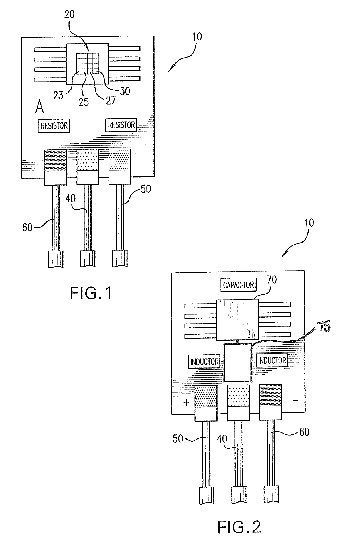
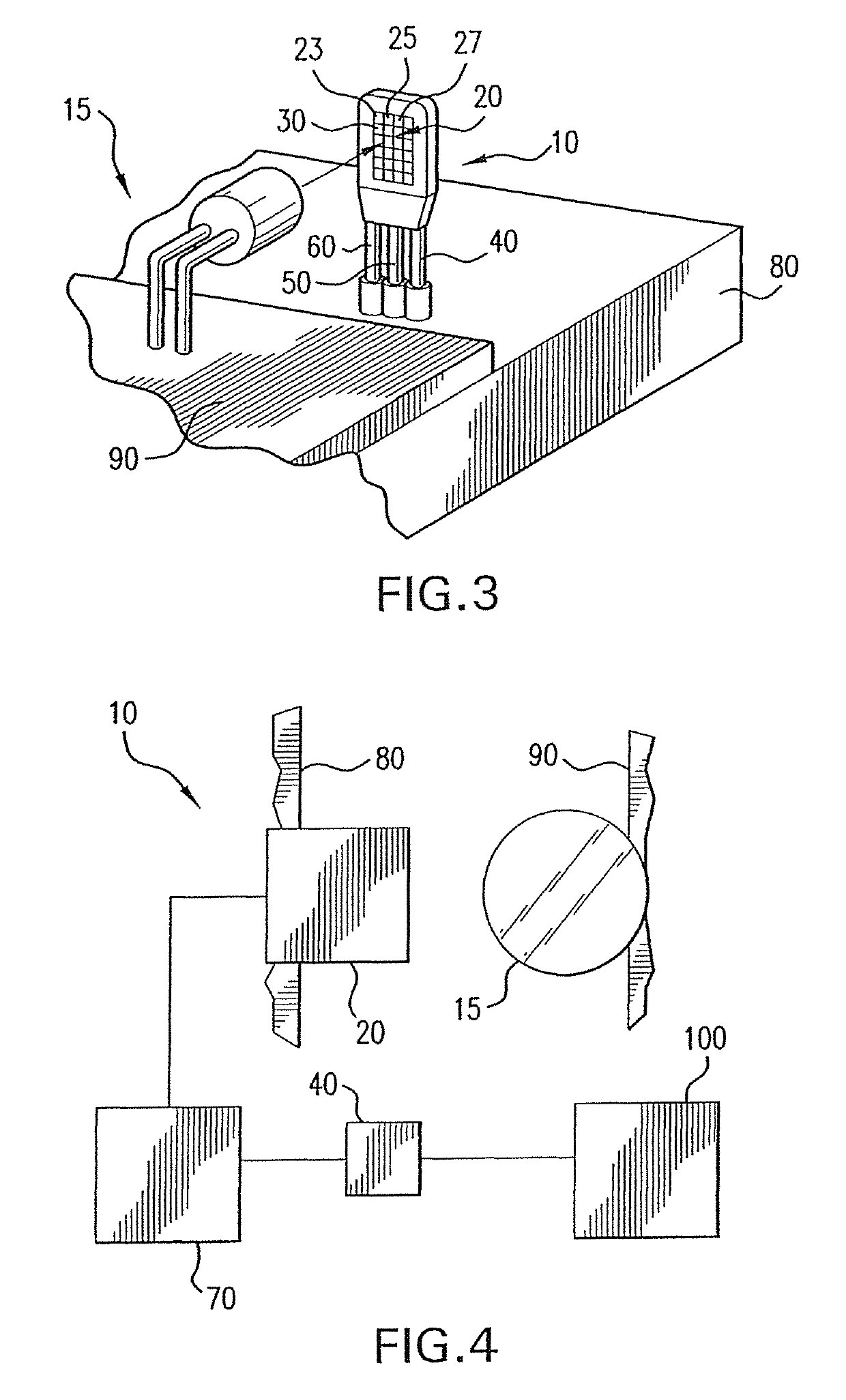
[0023]A system and apparatus for determining a presence and / or brightness and / or color of an light emitting diode (LED) in a printed circuit board where the LED is biased with a constant current (“DC Mode”) or is biased with current pulses (“Pulsing Mode”).

[0024]According to one preferred embodiment of this invention, an apparatus and system for determining a color and brightness of LED 15 in printed circuit board 90 is shown in FIGS. 1-4. LEDs 15 are typically used in printed circuit boards 90 and require verification and determination of their operation in a different manner than the traditional manner of verification of the placement and operation of integrated circuits within printed circuit board 90. LEDs 15 are available in clear / white and several common colors such as red, green and blue. Beyond mere verification of the operation of LED 15, it is also preferable, and an object of this invention, to determine the color and brightness of LED 15, in part to confirm that such LED...


PUM


Abstract

A method and apparatus for determining a color and brightness of an LED, when the LED is biased with a current pulse. The apparatus includes a sensor having a plurality of filters and an output probe connected to the sensor, the output probe providing a color output and a brightness output in a single signal. The sensor may further include an input probe connected to the sensor providing power and a ground probe connected to the sensor providing a grounded connection to the sensor. The plurality of filters in the sensor are preferably configured in a matrix array of color receptors having different colors. The method of this invention utilizes pulsing / dynamic sampling to determine a frequency and / or a brightness of the LED output.

Description

CROSS REFERENCE TO RELATED APPLICATION[0001]This application claims the benefit of U.S. Provisional Patent Application, Ser. No. 62 / 293,139, filed on 9 Feb. 2016. The Provisional Application is hereby incorporated by reference herein in its entirety and is made a part hereof, including but not limited to those portions which specifically appear hereinafter.BACKGROUND OF THE INVENTION[0002]Field of the Invention[0003]This invention relates to a method and apparatus for testing for the presence, brightness and / or color of a light emitting diode (LED) in a printed circuit board, where the LED is biased either with constant current or with a current pulse.[0004]Description of Related Art[0005]Printed circuit boards typically contain multiple components including: LEDs, resistors, capacitors, diode, fuse, processors, and similar such components. LEDs are often used as external signals, internal diagnostics and for other suitable applications. Typically, verification of the operation of a...

Claims


Application Information

Patent Timeline
Patent Type & Authority Patents(United States)
IPC IPC(8): G01J1/02G01J3/50G01J3/51G01J1/04G01J1/42G01J3/02
CPCG01J3/505G01J1/0204G01J3/0264G01J3/513G01J1/0492G01J2001/4252
Inventor CORROCHANO, DENIS
Owner NASA SOLUTIONS LLC
Why Eureka
Try Eureka