System and method for channel bonding in multiple antenna communication systems

a communication system and channel bonding technology, applied in the direction of pulse technique, amplitude demodulation, line-fault/interference reduction, etc., can solve the problems of increasing the cost of providing a separate rf chain for each transmit and receive antenna, and the overall system cost and power consumption may dramatically increas

Active Publication Date: 2005-05-19
AVAGO TECH INT SALES PTE LTD
View PDF88 Cites 87 Cited by
  • Summary
  • Abstract
  • Description
  • Claims
  • Application Information

AI Technical Summary

Problems solved by technology

Although increasing the number of transmit and / or receive antennas enhances various aspects of the performance of MIMO systems, the provision of a separate RF chain for each transmit and receive antenna increases costs.
It is thus apparent that as the number of transmit and receive antennas increases, overall system cost and power consumption may dramatically increase.

Method used


Image

  • System and method for channel bonding in multiple antenna communication systems
  • System and method for channel bonding in multiple antenna communication systems
  • System and method for channel bonding in multiple antenna communication systems

Examples


Embodiment Construction

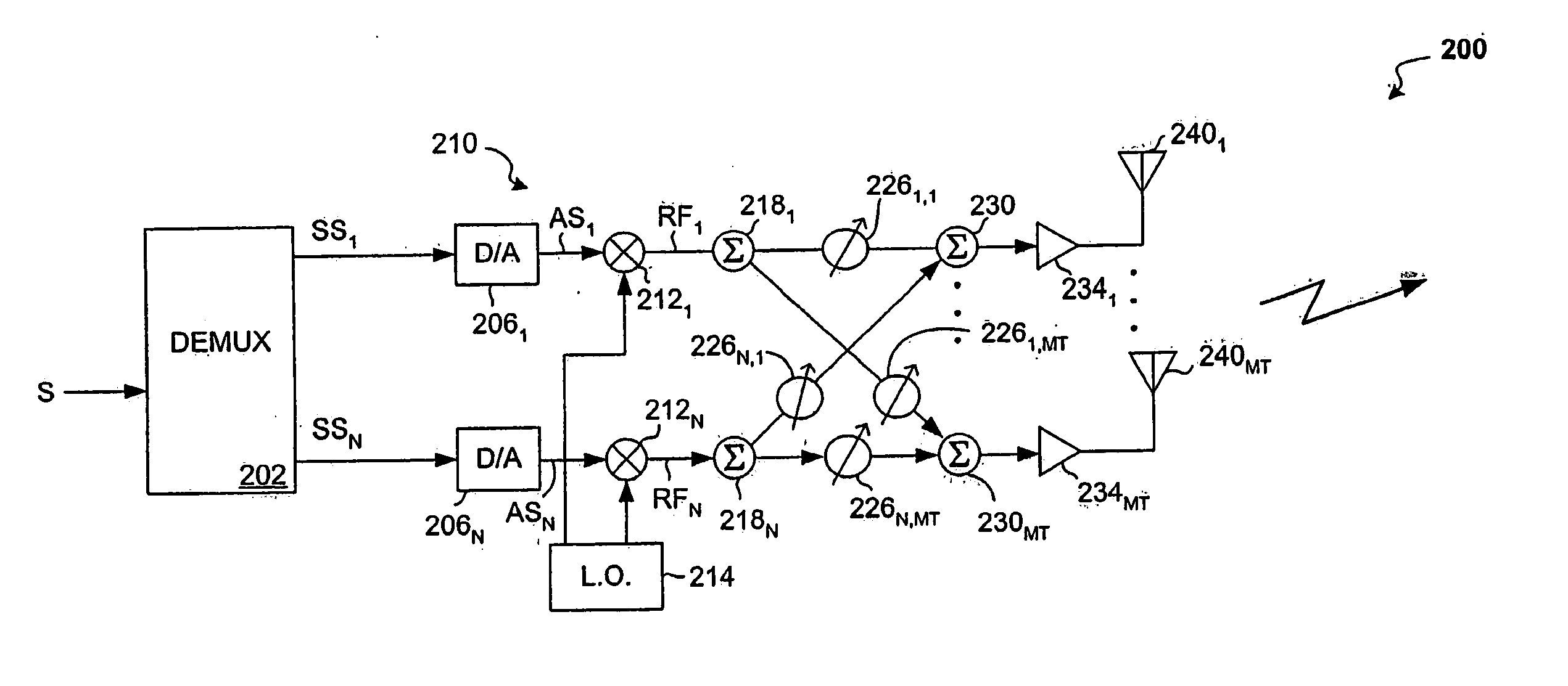
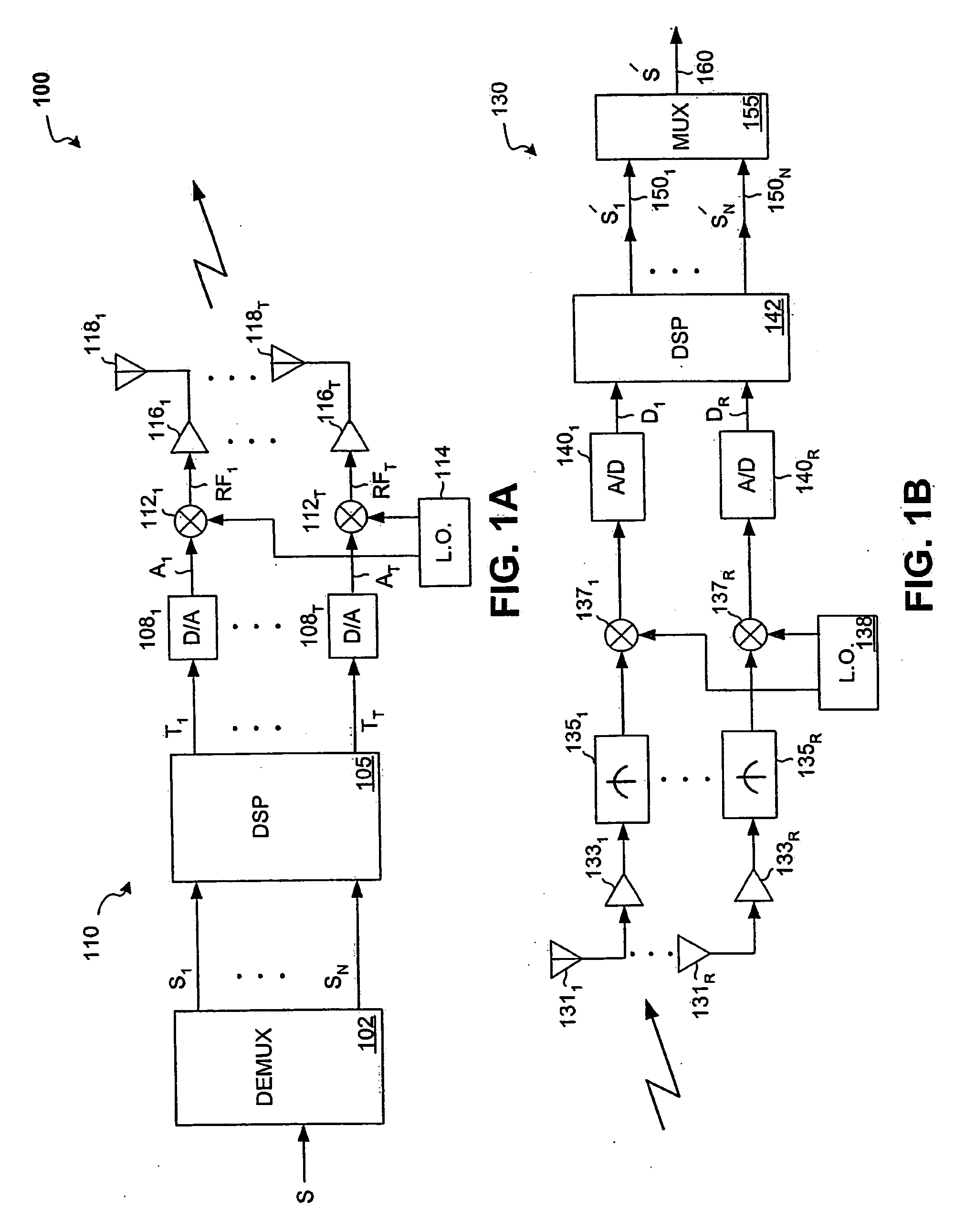
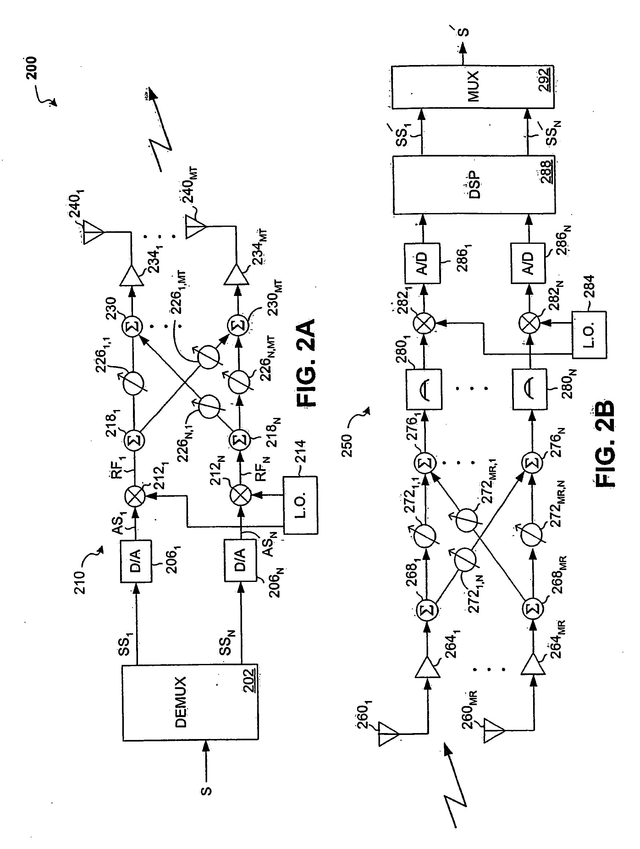
[0034] Some embodiments according to some aspects of the present invention may relate to channel bonding in multiple antenna communication systems.

[0035] Some embodiments according to some aspects of the present invention may be directed to systems and methods for data rate maximization with multi-antenna transmitters and / or receivers that employ, for example, one or more channel bonding strategies. Some embodiments according to some aspects of the present invention may provide, for example, a user signal, which is destined to be communicated between a multi-antenna transmitter and receiver and which may be allocated multiple logical channels in parallel for transmission and reception.

[0036] Some embodiments according to some aspects of the present invention may be applied within or in combination with, for example, multi-antenna transmitter and receiver structures adapted to process one or more information signals via baseband weighting and combining arrangements. Some embodiment...


PUM


Abstract

Systems and methods that provide channel bonding in multiple antenna communication systems are provided. In one embodiment, a method for signal transmission over a plurality of antennas of a transmitter may include, for example, one or more of the following: demultiplexing an input signal into a plurality of signal components; assigning each of the signal components to one of a plurality of logical channels; weighting each of the signal components with transmit baseband weight values; combining ones of the resultant weighted signal components to form a plurality of transmit weighted signals, each of the plurality of transmit weighted signals being assigned to one of the plurality of logical channels; and combining groups of the plurality of transmit weighted signals to form a plurality of output signals capable of being used to generate a plurality RF output signals.

Description

CROSS REFERENCE TO RELATED APPLICATIONS [0001] This application is a continuation-in-part of U.S. patent application Ser. No. 10 / 801,930 (Attorney Docket No. 16136US02) filed on Mar. 16, 2004, which claims priority to and claims benefit from U.S. Patent Application Ser. No. 60 / 456,023 (Attorney Docket No. 16136US01) filed on Mar. 17, 2003. [0002] This application is also a continuation-in-part of U.S. patent application Ser. No. 10 / 835,255 (Attorney Docket No. 16137US02) filed on Apr. 29, 2004, which claims priority to and claims benefit from U.S. Patent Application Ser. No. 60 / 467,295 (Attorney Docket No. 16137US01) filed on May 1, 2003. [0003] This application is also a continuation-in-part of U.S. patent application Ser. No. 10 / 891,443 (Attorney Docket No. 16108US02) filed on Jul. 13, 2004, which claims priority to and claims benefit from U.S. Patent Application Ser. No. 60 / 488,845 (Attorney Docket No. 16108US01) filed on Jul. 21, 2003. [0004] This application is also a continuat...

Claims


Application Information

Patent Timeline
Patent Type & Authority Applications(United States)
IPC IPC(8): H04L1/02
CPCH04B7/0615H04W52/42H04B7/0848H04B7/0842
Inventor CATREUX-ERCES, SEVERINEERCEG, VINKOROUX, PIETERROOYEN, PIETER VANWINTERS, JACK
Owner AVAGO TECH INT SALES PTE LTD
Why Eureka
Try Eureka