
Closed vessel for radioactive substance, seal-welding method for closed vessel, and exhaust system used for seal-welding method

Inactive Publication Date: 2005-05-19
MITSUBISHI HEAVY IND LTD
View PDF30 Cites 1 Cited by
  • Summary
  • Abstract
  • Description
  • Claims
  • Application Information

AI Technical Summary

Benefits of technology

[0016] According to the closed vessel for a radioactive substance constructed in this manner, steam can be prevented from getting into the welding portion by filling into or running the shield gas through the space portion of the lid as the lid means is welded. Thus, the lid can be securely welded without involving any weld defects that are attributable to steam.
[0017] Since the gap between the shielding plate and the vessel body is sealed, moreover, steam can be more securely prevented from getting into the welding portion through the gap as the lid means is welded. In consequence, the lid means can be securely welded without involving any weld defects that are attributable to steam. Thus, the resulting closed vessel provides improved integrity and high radiation shielding properties.
[0020] According to the seal-welding method for a closed vessel of the invention, moreover, the lid has an outer peripheral portion adjacently opposed to the inner peripheral surface of the vessel body, the outer peripheral portion including a welding portion welded to the inner peripheral surface of the vessel body and a space portion located on the bottom side of the vessel body with respect to the welding portion, and a shield gas is filled into or run through the space portion, thereby preventing the steam from getting into the welding portion, as the lid means is welded.
[0021] According to the seal-welding method for a closed vessel described above, the vessel body is evacuated to discharge steam as the lid is welded, whereby the steam can be prevented from getting into the welding portion. Thus, the lid can be securely welded without involving any weld defects.
[0022] Further, the steam can be more securely prevented from getting into the welding portion in a manner such that the shield gas is filled into or run through the space portion of the lid as the lid is welded. The resulting closed vessel enjoys high closeness and. satisfactory radioactive substance sealing properties without involving any weld defects.
[0024] According to the exhaust system constructed in this manner, the vessel body can be simultaneously exhausted and charged by using the one discharge hole. More specifically, the air containing steam in the vessel body is discharged through the exhaust port by means of the suction device, and in concert with this, air is charged into the vessel body through the charging pipe, whereby the internal pressure of the vessel body is regulated. Thus, the steam that is generated in the vessel body can be discharged from the vessel body, so that a large quantity of steam can be prevented from getting into the welding portion. Even though radiation from the radioactive substance is intercepted by means of the water during the welding operation, therefore, satisfactory circumstances can be enjoyed without involving any voids in the welding portion, and improvement of the welding accuracy can be expected.

Problems solved by technology

However, the welding operation takes so much time that the cooling water in the vessel body is heated by the spent fuel assemblies and evaporated gradually.
As this is done, however, steam gets into the gap between the inner surface of the vessel body and the primary lid, as a welding portion, so that weld defects such as voids are inevitably formed in the welding portion.
These weld defects lower the strength of the welding portion, and a radioactive substance leaks from the defective portions.
Thus, it is hard to maintain the integrity or radioactive substance sealing performance of the canister.

Method used


Image

  • Closed vessel for radioactive substance, seal-welding method for closed vessel, and exhaust system used for seal-welding method
  • Closed vessel for radioactive substance, seal-welding method for closed vessel, and exhaust system used for seal-welding method
  • Closed vessel for radioactive substance, seal-welding method for closed vessel, and exhaust system used for seal-welding method

Examples


first embodiment

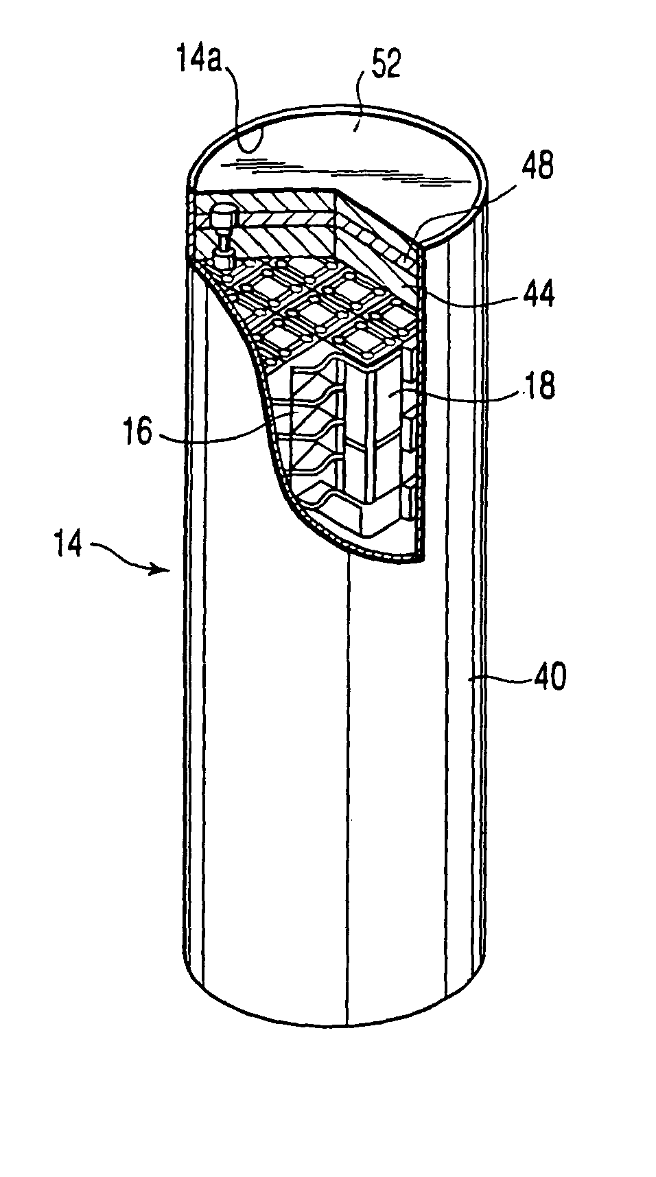
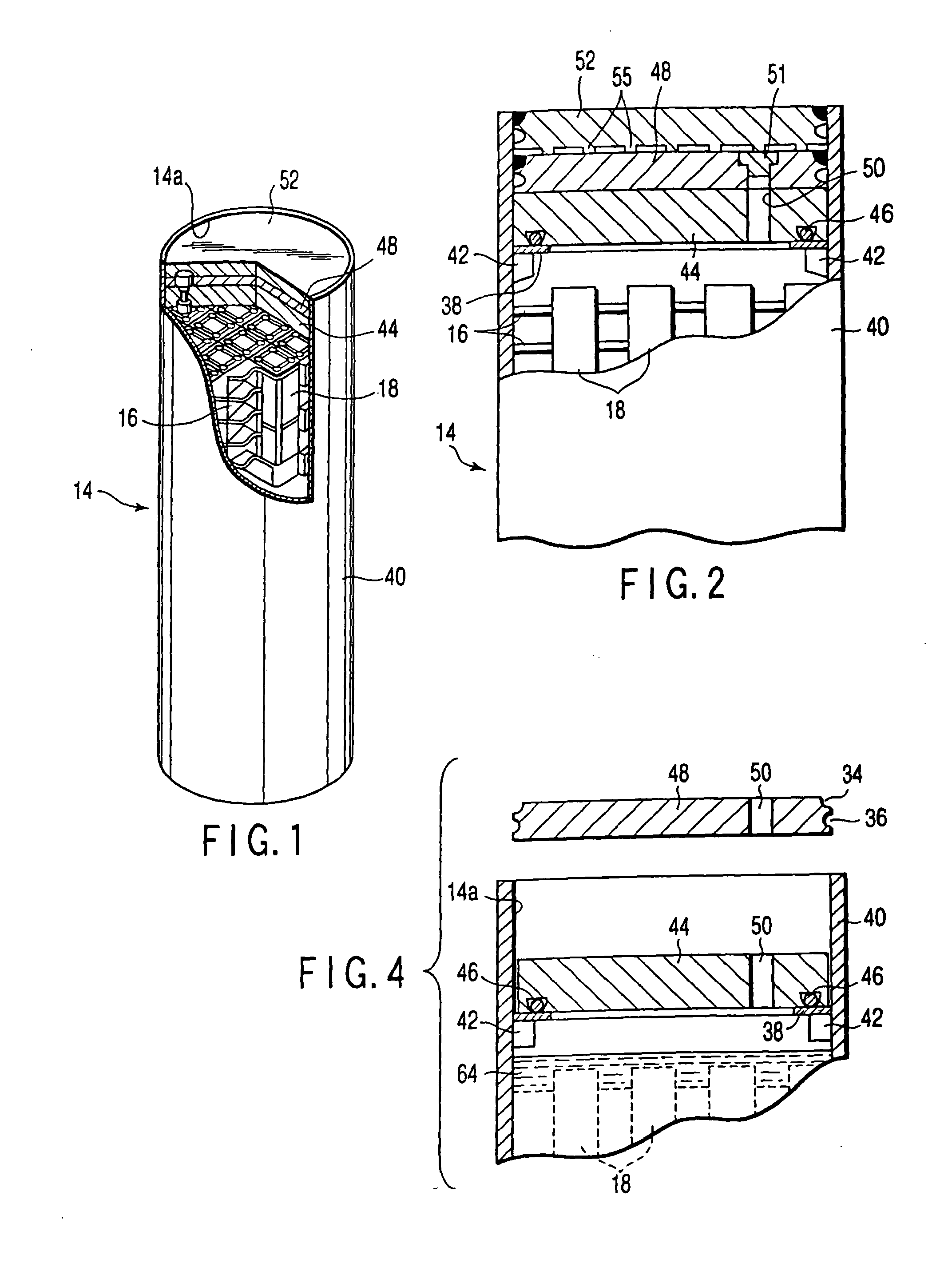
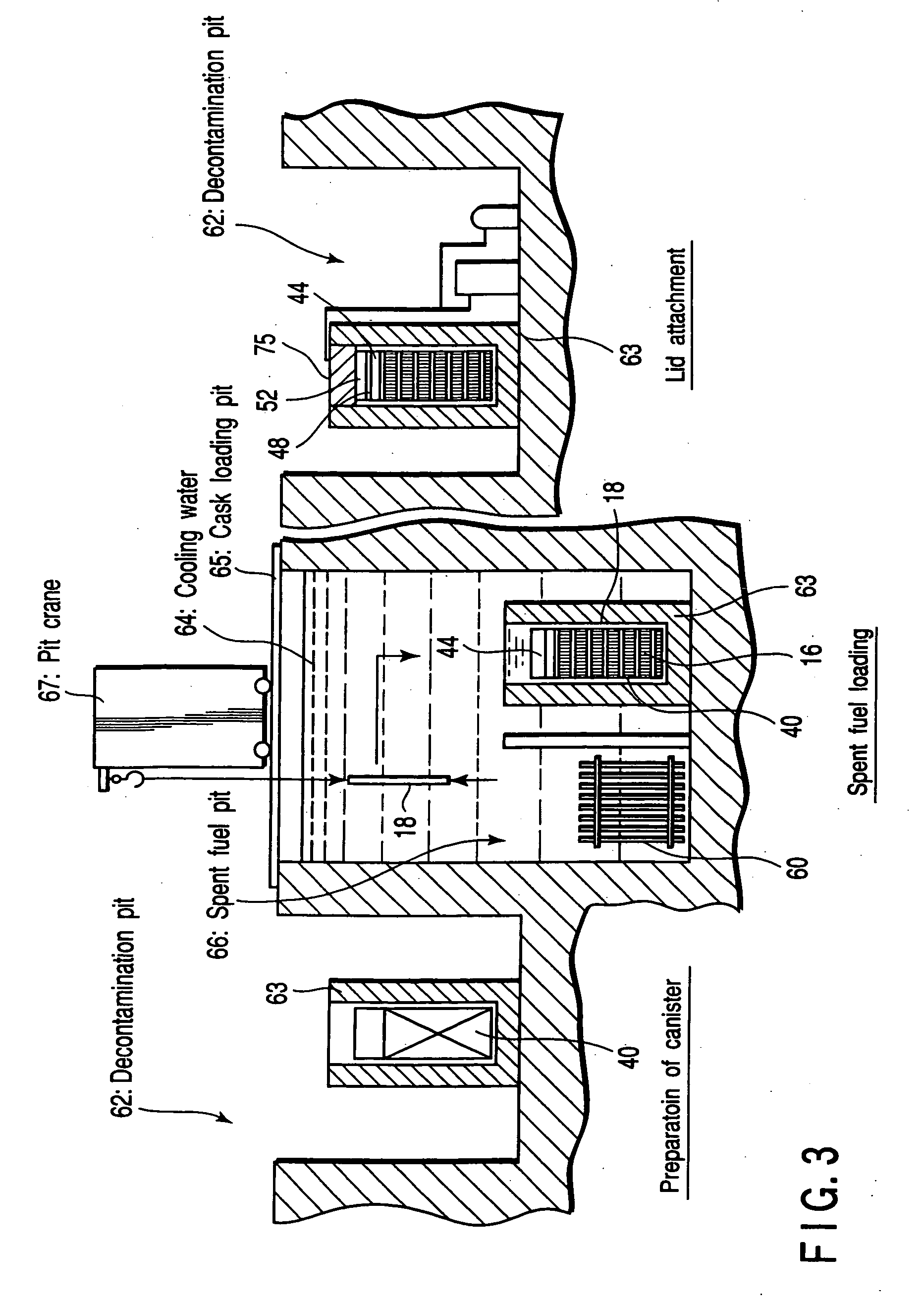
[0037] A canister according to the present invention will now be described in detail with reference to the accompanying drawings.

[0038] As shown in FIGS. 1 and 2, a canister 14 for use as a metallic closed vessel comprises a substantially cylindrical vessel body 40 that is closed at the bottom and has a top opening 14a. The vessel body 40 is formed of a metal such as stainless steel. A plurality of spent fuel assemblies 18 are sealed in the vessel body 40 in a manner such that they are supported by a basket 16. These spent fuel assemblies 18 are formed of a spent fuel from a reactor, for example, and contain a radioactive substance that involves heat release attributable to decay heat and generation of radiation. The canister 14 has a weld-sealed structure to prevent the contained radioactive substance leaking out.

[0039] More specifically, a plurality of support blocks 42, e.g., four in number, are fixed on the inner peripheral surface of the upper end portion of the vessel body 40...

second embodiment

[0073] Also in the second embodiment, therefore, steam can be prevented from flowing into the welding portion as the primary lid 48 is welded, so that the primary lid 48 can be securely welded without involving any weld defects that are attributable to steam. Thus, the resulting canister enjoys improved radiation shielding properties.

[0074] Also in the second embodiment, moreover, only one of the operations for discharging steam by means of the exhaust system 5 and intercepting steam by means of the shield gas may be carried out with the same effect. In this case, steam can be prevented from reaching the welding portion, and therefore, generation of weld defects can be prevented. Thus, the resulting canister provides high shielding properties.

[0075] Additional advantages and modifications will readily occur to those skilled in the art. Therefore, the invention in its broader aspects is not limited to the specific details and representative embodiments shown and described herein. Ac...


PUM


Abstract

A primary lid is set in a top opening of a vessel body that contains radioactive substance, and closes the top opening. The peripheral edge portion of the primary lid is welded to the inner peripheral surface of the vessel body. As the primary lid is welded, steam in the vessel body is discharged to the outside through a discharge hole in the primary lid, and a shield gas is filled into or run through a space in the outer peripheral portion of the primary lid, so as to prevent the steam from flowing into the welding portion.

Description

CROSS-REFERENCE TO RELATED APPLICATIONS [0001] This application is based upon and claims the benefit of priority from the prior Japanese Patent Application No. 2001-200174, filed Jun. 29, 2001, the entire contents of which are incorporated herein by reference. BACKGROUND OF THE INVENTION [0002] 1. Field of the Invention [0003] The present invention relates to a metallic closed vessel, or a so-called canister, in which a radioactive substance that involves heat release is sealed, a seal-welding method for the closed vessel, and an exhaust system used for the seal-welding method. [0004] 2. Description of the Related Art [0005] Highly radioactive substances represented by spent fuels from nuclear reactors are destructured and reprocessed in order to recover plutonium or some other useful substances that can be used again as fuels. These spent fuels are contained in closed places before they are reprocessed. Known containing methods for these highly radioactive substances include a wet ...

Claims


Application Information

Patent Timeline
IPC IPC(8): B23K9/00G21F5/00G21C19/06G21F5/005G21F5/008G21F5/12
CPCG21F5/005G21F5/12G21Y2002/104G21Y2004/40G21Y2002/303G21Y2002/501G21Y2004/30G21Y2002/206G21F5/008
Inventor MATSUNAGA, KENICHIABE, GANJIMURAKAMI, KAZUOUE, KOICHISHIGE, TAKASHIKITA, ETSURYOINOUE, SHIZUOMANDAI, TSUNEO
Owner MITSUBISHI HEAVY IND LTD
Learn More