
A ray tracing-based optical camera simulation imaging method and system

An optical system and ray tracing technology, applied in design optimization/simulation, TV system components, image communication, etc., can solve problems such as incomplete and incapable simulation of photoelectric conversion systems of remote sensing cameras, and achieve high closeness and realization Short-time optical system modeling and calculation, the effect of improving the calculation speed

Active Publication Date: 2019-06-14
BEIJING INSTITUTE OF TECHNOLOGYGY
View PDF3 Cites 0 Cited by
  • Summary
  • Abstract
  • Description
  • Claims
  • Application Information

AI Technical Summary

Problems solved by technology

[0005] However, MTF and PSF describe the frequency or spatial response characteristics of CCD (charge-coupled device) imaging. However, in the imaging process, there are also radiation response characteristics, such as detector responsivity, non-uniformity, etc., only using MTF or The way PSF is described is incomplete
Therefore, the traditional simulation imaging methods based on MTF or PSF cannot realize comprehensive and systematic simulation of the photoelectric conversion system of remote sensing cameras.

Method used


Image

  • A ray tracing-based optical camera simulation imaging method and system
  • A ray tracing-based optical camera simulation imaging method and system
  • A ray tracing-based optical camera simulation imaging method and system

Examples


Embodiment Construction

[0055] Various exemplary embodiments of the present invention will now be described in detail with reference to the accompanying drawings. It should be noted that the relative arrangements of components and steps, numerical expressions and numerical values ​​set forth in these embodiments do not limit the scope of the present invention unless specifically stated otherwise.

[0056] The following description of at least one exemplary embodiment is merely illustrative in nature and in no way taken as limiting the invention, its application or uses.

[0057] Techniques, methods and devices known to those of ordinary skill in the relevant art may not be discussed in detail, but where appropriate, such techniques, methods and devices should be considered part of the description.

[0058] In all examples shown and discussed herein, any specific values ​​should be construed as exemplary only, and not as limitations. Therefore, other instances of the exemplary embodiment may have dif...


PUM


Abstract

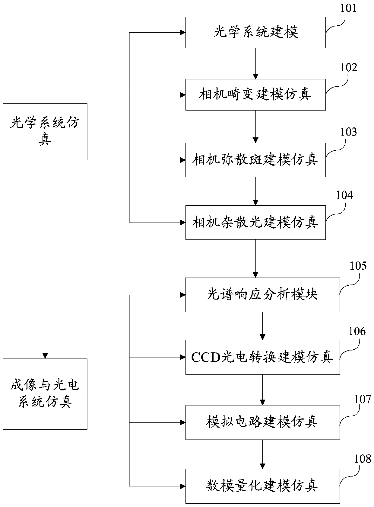
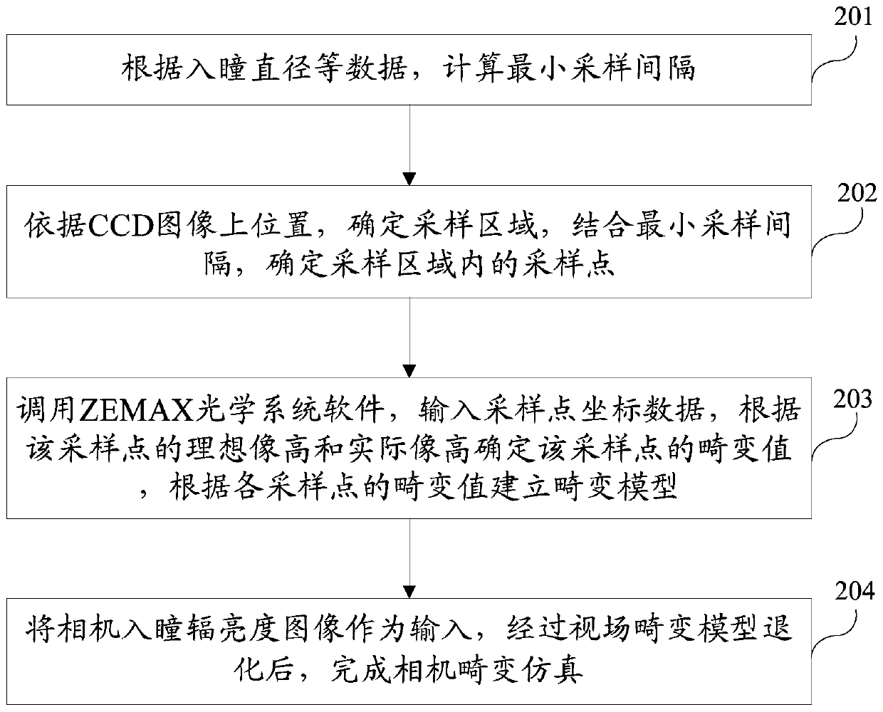
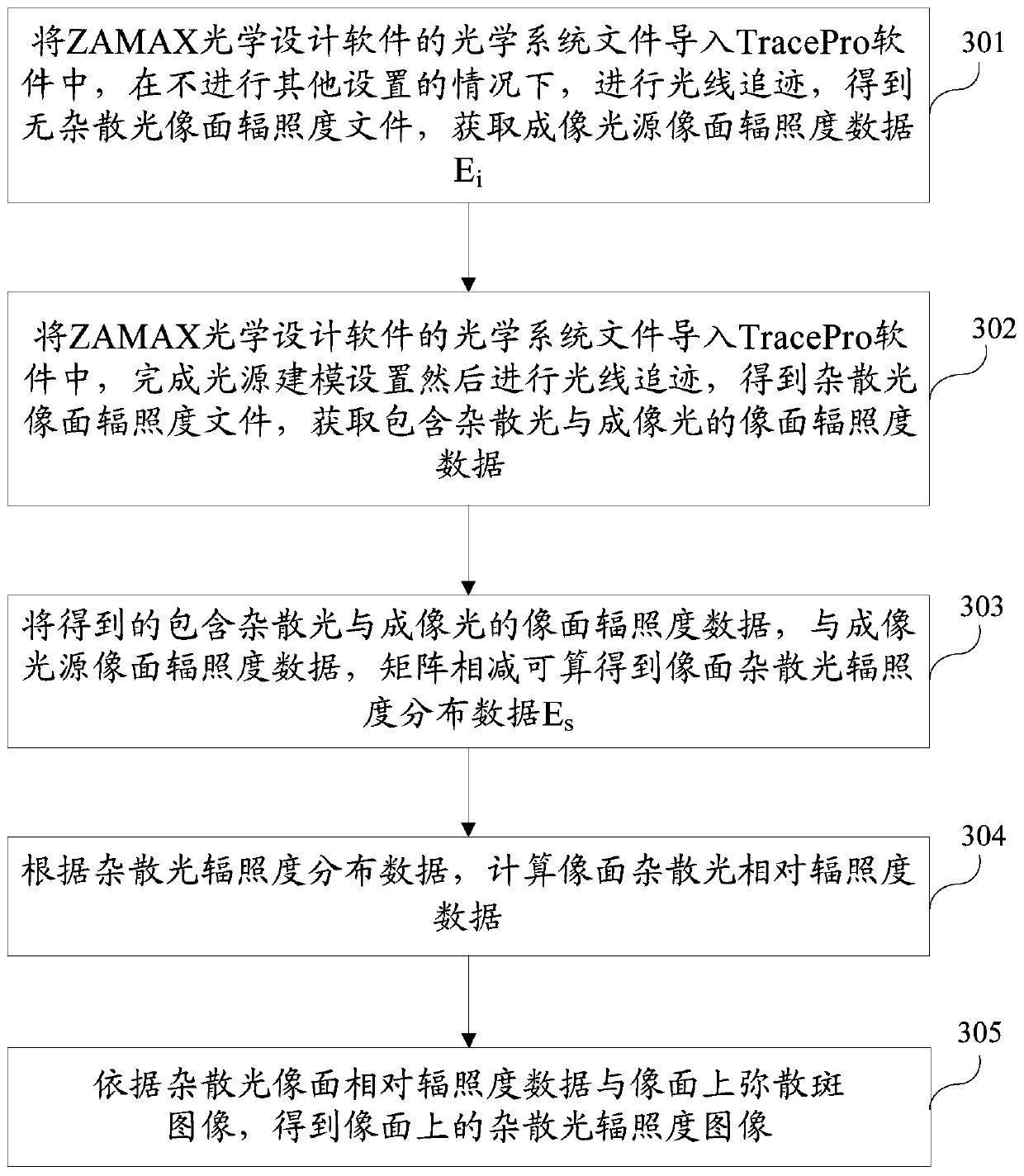
The present invention proposes an optical camera simulation imaging method and system based on ray tracing, the method includes: optical system simulation and imaging and photoelectric system simulation; optical system simulation includes: optical system modeling, camera distortion modeling simulation, camera dispersion Spot modeling and simulation and camera stray light modeling and simulation; imaging and photoelectric system simulation includes spectral response analysis module, CCD photoelectric conversion modeling and simulation, analog circuit modeling and simulation, and digital-to-analog quantization modeling and simulation. The present invention comprehensively considers the influence factors of the optical system of the remote sensing camera and the CCD imaging system on the imaging result, and establishes a detailed and complete database of remote sensing camera parameters, so that the simulated image is closer to the real image and has higher simulation accuracy.

Description

technical field [0001] The present invention relates to the technical field of optical system simulation imaging, and more particularly, to a modeling and simulation imaging method and system of an optical camera based on ray tracing. Background technique [0002] Satellite remote sensing imaging technology is an important technology in the field of remote sensing, and it is widely used in military and national economic fields, such as military reconnaissance, missile early warning, environmental monitoring, resource investigation, etc. The research and development of satellite remote sensing imaging technology has a strong demand and application background in both civilian and military fields. As an important part of the remote sensing satellite, the optical system can simulate the optical system of the remote sensing satellite. At the beginning of the satellite design, a reliable and scientific imaging simulation system can be established, and it will move towards high pre...

Claims


Application Information

Patent Timeline
Patent Type & Authority Patents(China)
IPC IPC(8): G06F17/50H04N5/372
CPCG06F30/20H04N25/71
Inventor 陈小梅谷琼琼杨德运谭泓
Owner BEIJING INSTITUTE OF TECHNOLOGYGY
Learn More