Method and apparatus for detecting positions of center points of circular patterns

a technology of center points and circular patterns, applied in the field of methods and apparatus for detecting the position of center points of circular patterns, can solve the problems of affecting the noise of the above-mentioned techniques, and achieve the effect of free from the adverse effects of nois

Active Publication Date: 2005-05-19
FUJIFILM HLDG CORP +1
View PDF5 Cites 45 Cited by
  • Summary
  • Abstract
  • Description
  • Claims
  • Application Information

AI Technical Summary

Benefits of technology

[0006] The primary object of the present invention is to provide a method of detecting a position of a center point of a circular pattern, w...

Problems solved by technology

Therefore, the aforesaid techniques for detecting the position of the center point of the circular pattern wi...

Method used


Image

  • Method and apparatus for detecting positions of center points of circular patterns
  • Method and apparatus for detecting positions of center points of circular patterns
  • Method and apparatus for detecting positions of center points of circular patterns

Examples


first embodiment

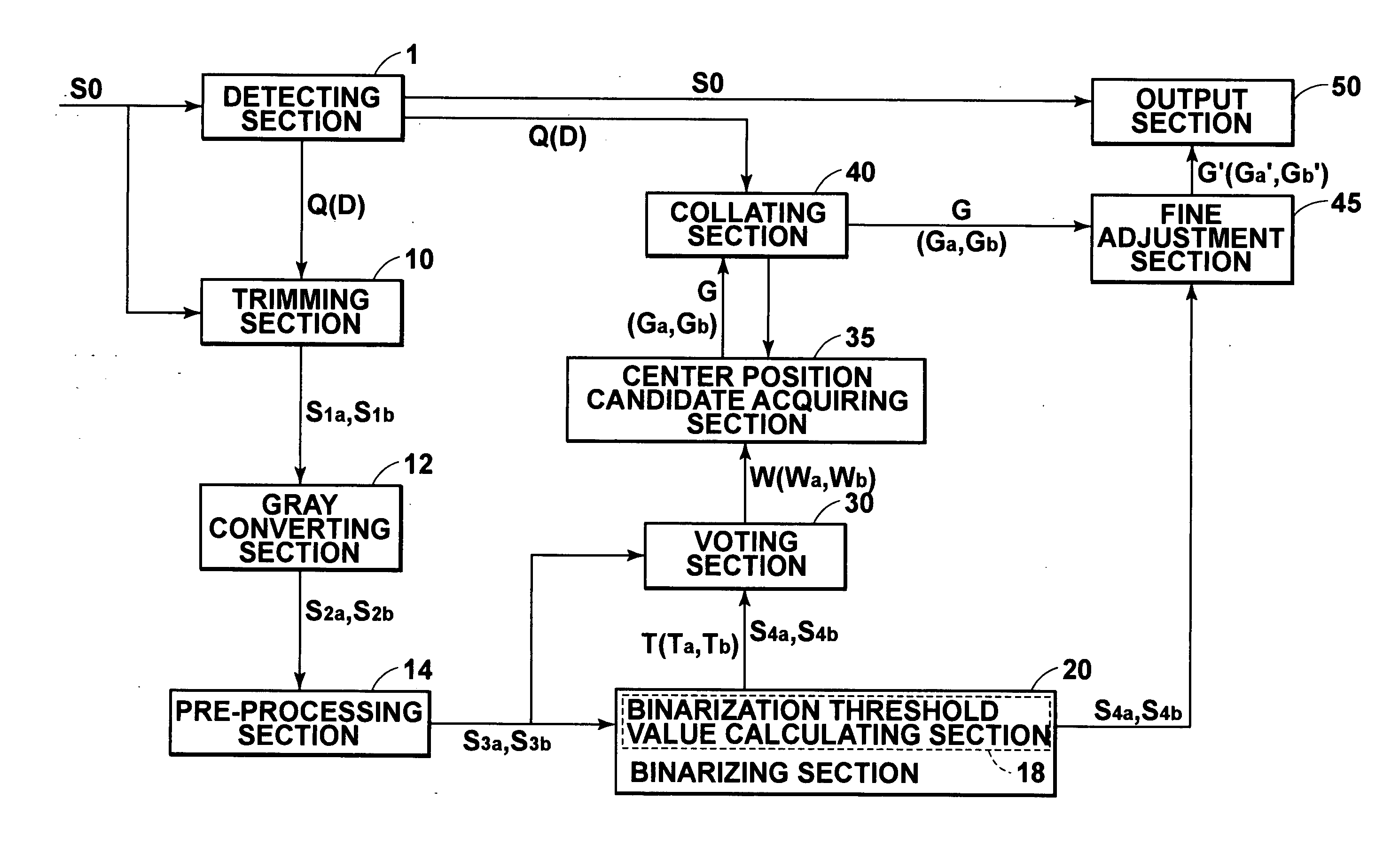
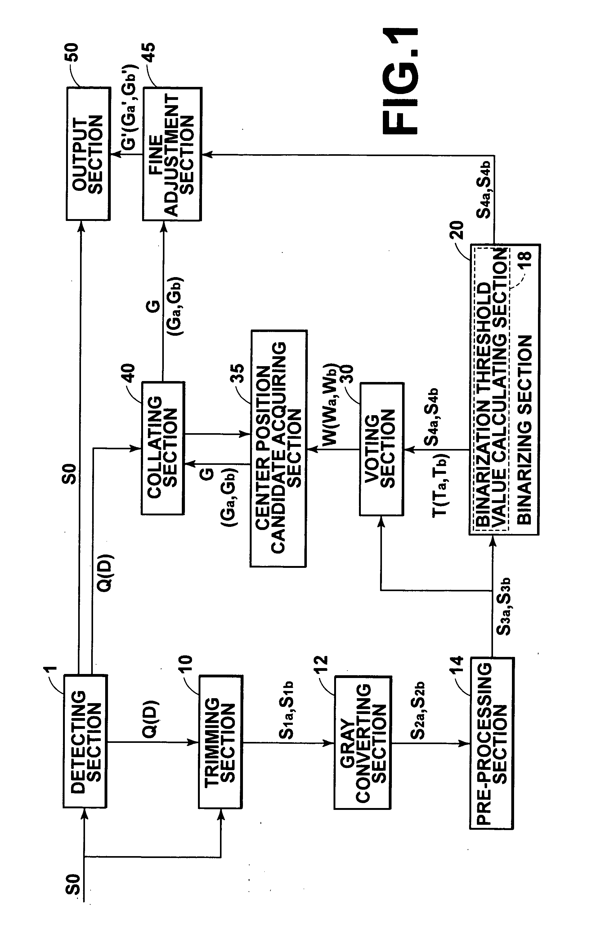
[0200]FIG. 18 is a flow chart showing how processing is performed in the apparatus for detecting a position of a center point of a pupil pattern in accordance with the present invention shown in FIG. 1.

[0201] As illustrated in FIG. 18, firstly, in a step S110, the detecting section 1 performs the operation for detecting a face image fro the photographic image S0. Also, in a step S115, the detecting section makes the discrimination as to whether a face image is or is not contained in the photographic image S0. In cases where it has been discriminated in the step S115 that a face image is not contained in the photographic image S0, the image signal representing the photographic image S0 is fed out from the detecting section 1 into the output section 50. In cases where it has been discriminated in the step S115 that a face image is contained in the photographic image S0, in a step S120, the positions of the two eye patterns in the photographic image S0 are detected by the detecting sec...

second embodiment

[0209] In FIG. 19, the voting section 30′ firstly performs the voting of the coordinates of each of pixels (having a pixel value of 1) in the binary image S4 onto the Hough space corresponding to annuluses, which Hough space is defined by the coordinate system having the X coordinate axis for the center point of the circle, the Y coordinate axis for the center point of the circle, and the r coordinate axis for the radial direction. The voting section 30′ calculates the vote value of each of voting positions having coordinates (X, Y, r) on the Hough space. A plurality of vote values are obtained with respect to the voting positions having the coordinates (X, Y, r) on the Hough space. Ordinarily, in cases where a vote is given by a certain pixel with respect to one voting position, a value of 1 may be added to the voting value of the voting position. The number of votes having been given to each voting position may thus be calculated cumulatively, and the vote value of each voting pos...


PUM


Abstract

Voting of coordinates of each pixel in a photographic image onto a Hough space corresponding to annuluses is performed, the Hough space being defined by a coordinate system having an X coordinate axis for a circle center point, a Y coordinate axis for a circle center point, and an r coordinate axis for a radial direction. A vote value of each voting position having coordinates (X, Y, r) on the Hough space is acquired as a first integrated vote value from a calculation of a number of votes given to each voting position. A position represented by (X, Y) coordinate values of a voting position associated with the largest first integrated vote value is detected as the position of the center point of the circular pattern.

Description

BACKGROUND OF THE INVENTION [0001] 1. Field of the Invention [0002] This invention relates to a method and apparatus for detecting a position of a center point of a circular pattern, such as a pupil pattern, from a digital photographic image. This invention also relates to a computer program for causing a computer to execute the method of detecting a position of a center point of a circular pattern. [0003] 2. Description of the Related Art [0004] Operations for detecting positions of center points of circular patterns from digital photographic images have heretofore been performed in various fields, such as detection of positions of center points of circular patterns of circular mechanical parts and detection of positions of center points of pupil patterns in photographic images of faces. Heretofore, various techniques, such as template matching techniques and Hough transform techniques, have been utilized for detecting circular patterns from digital photographic images of objects. ...

Claims


Application Information

Patent Timeline
IPC IPC(8): G06V10/48
CPCG06K9/4633G06V10/48
Inventor YONAHA, MAKOTOCHEN, TAO
Owner FUJIFILM HLDG CORP
Why Eureka
Try Eureka