Cervical traction device

a traction device and cervical technology, applied in the field of cervical traction devices, can solve the problems of difficult to obtain the desired wedge adjustment, device does not have any mechanism to adjust the angle of the entire device, and the traction device is expensiv

Inactive Publication Date: 2005-05-19
CARE REHAB & ORTHOPEDIC PRODS
View PDF24 Cites 14 Cited by
  • Summary
  • Abstract
  • Description
  • Claims
  • Application Information

AI Technical Summary

Problems solved by technology

However, such traction device is expensive.
This rotation, though, may make it difficult to obtain a desired adjustment of the wedges.
These same devices do not have any mechanism to adjust the angle of the entire device, or other mechanisms to ensure ease of adjustment with the confidence that such adjustment will remain in a locked position.

Method used


Image

  • Cervical traction device
  • Cervical traction device
  • Cervical traction device

Examples


Embodiment Construction

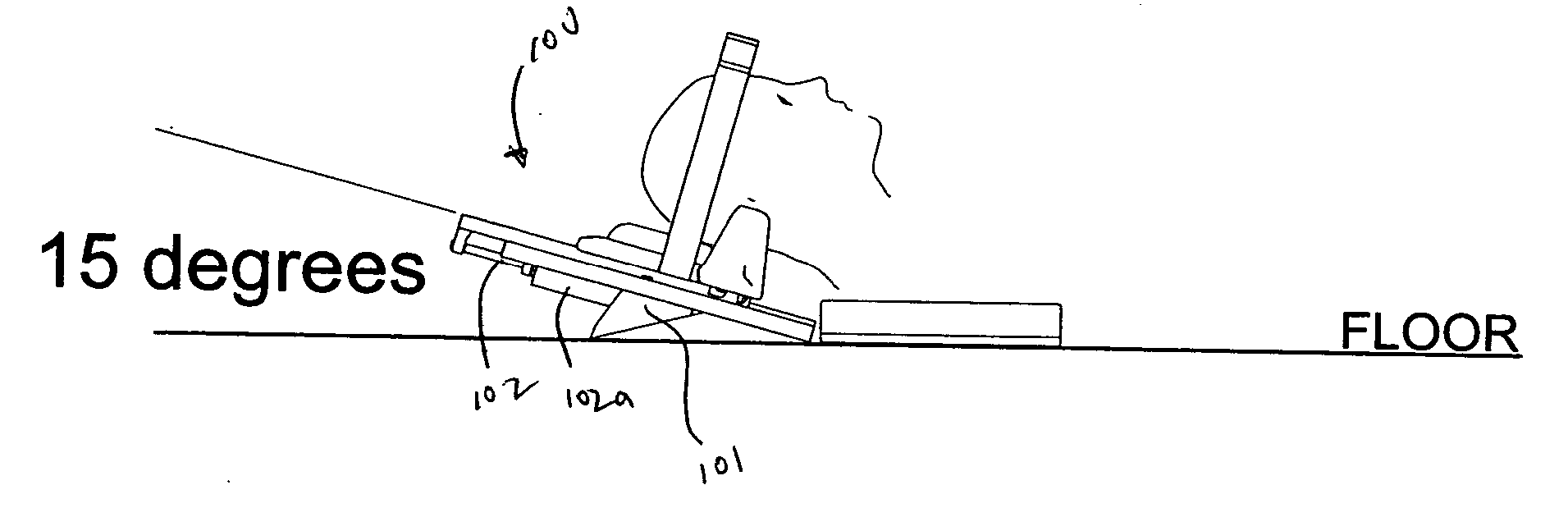
[0016] The invention is directed to a cervical traction device. The cervical traction device is adjustable at different angles and also includes adjustable wedge supports, in addition to other features.

Cervical Traction Device

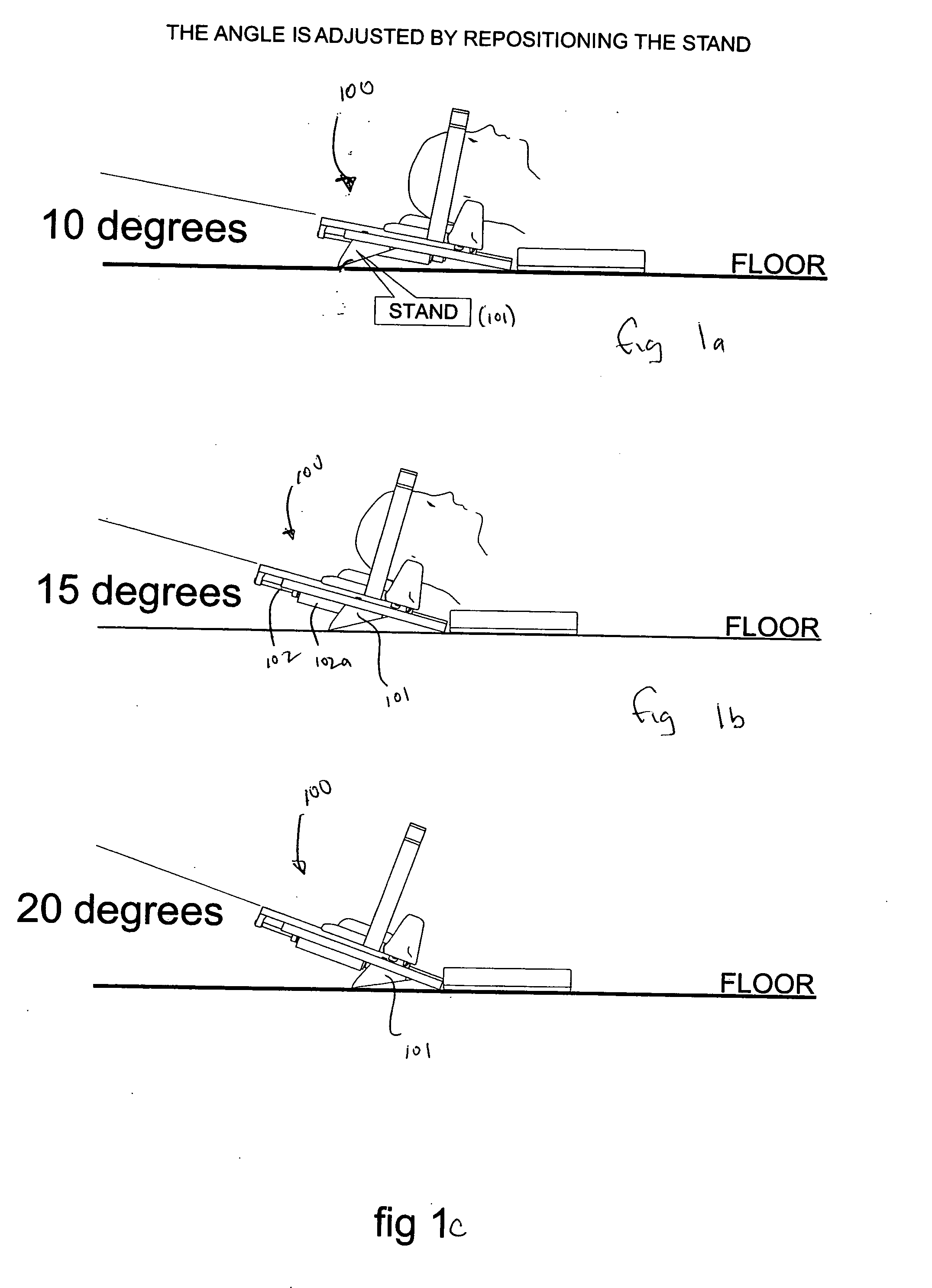
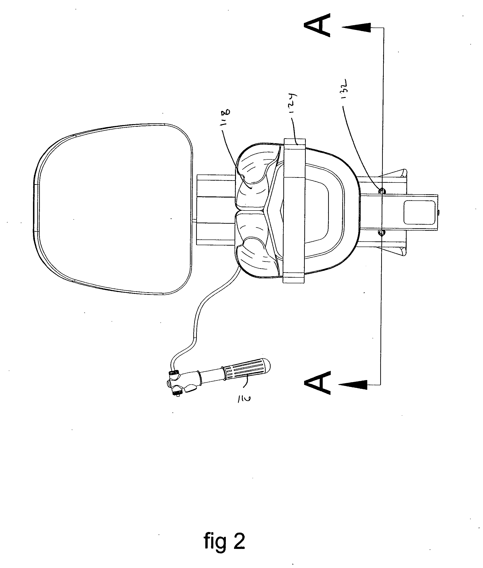
[0017] Referring now to the figures, a schematic diagram of the cervical traction device is shown. The cervical traction device 100 includes several different adjustable angles such as 10 degrees, 15 degrees and 20 degrees. It should be understood, though, that other angles of adjustment, with relation to the floor, are also contemplated by the invention, and that the adjustable angles shown herein are provided for illustrative purposes. The cervical traction device is adjustable via a stand 101 positioned underneath a movable carriage mounted on a stationary track. The carriage is slidably mounted along a support track via a pneumatic cylinder structure. The carriage includes a head rest or support pad.

[0018] In the cervical traction configuration, a pneuma...


PUM


Abstract

A traction device, comprising a stationary support and a movable carriage mounted on the stationary support. A mechanism is provided for moving the moveable carriage between a first position and a second position. A wedge system is mounted to the moveable carriage and a stand is adjustably mounted to the stationary support. The stand provides different adjustable angles for the wedge system.

Description

CROSS REFERENCE TO RELATED APPLICATIONS [0001] This application claims priority to U.S. Provisional Application Ser. No. 60 / 519,793, filed on Nov. 14, 2003, which is incorporated herein by reference.FIELD OF THE INVENTION [0002] The invention generally relates to a cervical traction device and, more particularly, to a cervical traction device having adjustable wedges and stand. BACKGROUND OF THE INVENTION [0003] Traction devices are used to relieve pressure on inflamed or enlarged nerves. Cervical and lumbar or spinal traction are the most common type of devices. When correctly performed, the traction devices can relieve pain in the neck and the spine by, for example, straightening the curvature of the spine or stretching of the spinal and cervical musculature. [0004] Portable traction devices are now becoming very popular for in home traction devices. This allows patients to perform traction therapy without leaving their homes, or expending large sums of money for a healthcare prov...

Claims


Application Information

Patent Timeline
Patent Type & Authority Applications(United States)
IPC IPC(8): A61F5/00
CPCA61F5/055A61H1/0296A61H2201/1253A61H2201/1664A61H2201/0192A61H2201/1607A61H2201/1246A61H2203/0456A61H2201/0157
Inventor HUNT, CHRISTIANBOGHOSIAN, ARA
Owner CARE REHAB & ORTHOPEDIC PRODS
Why Eureka
Try Eureka