

Roof for manure storage tank
a manure storage tank and cover technology, applied in the direction of manure treatment, building roofs, building components, etc., can solve the problems of difficult access to the manure storage tank for emptying the storage tank, inability to provide ventilation of the storage tank, and limited life span of the inflatable cover member
- Summary
- Abstract
- Description
- Claims
- Application Information
AI Technical Summary
Benefits of technology
Problems solved by technology
Method used
Image

Examples
Embodiment Construction
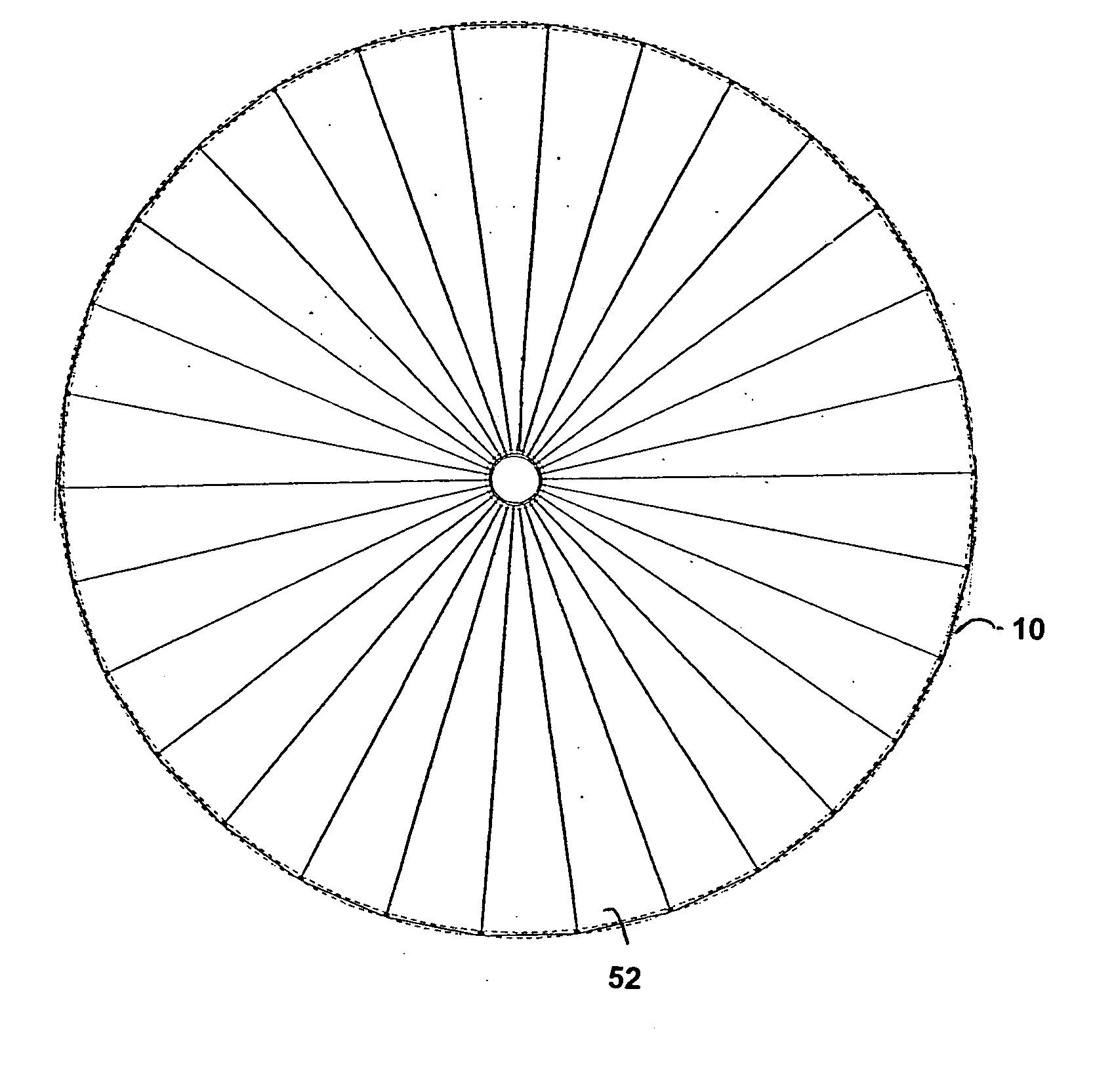
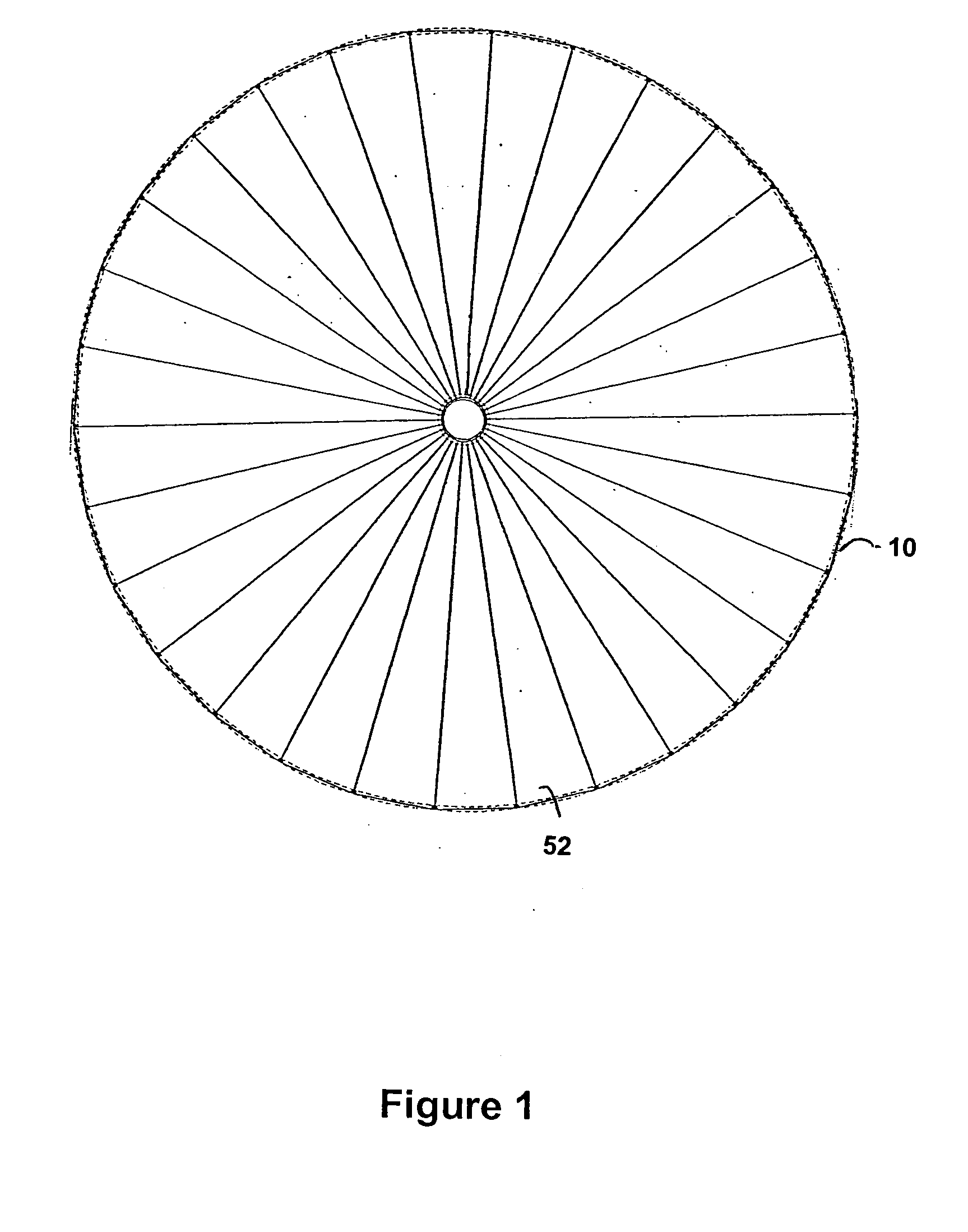
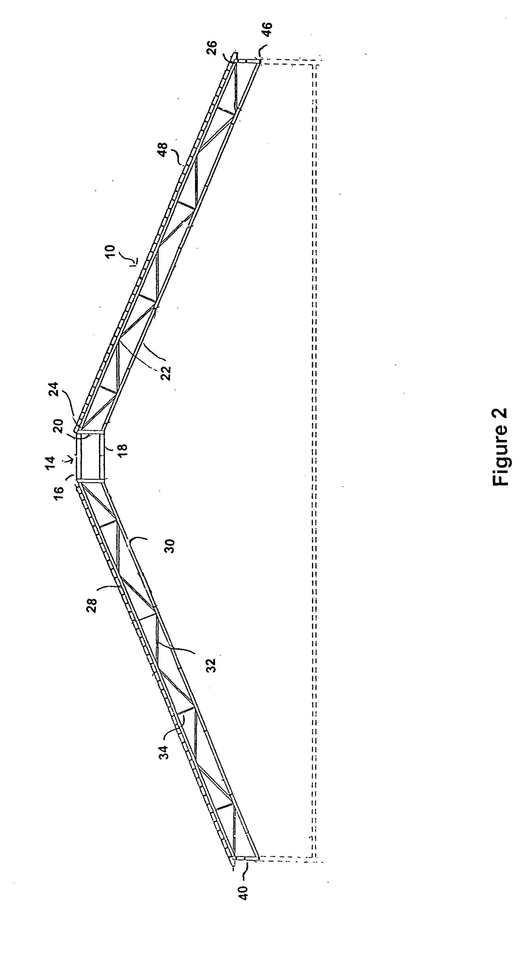
[0013] The roof 10 is adapted to cover manure storage tank 12 having a generally cylindrical wall structure. The roof 10 has a frusto-conical configuration. As illustrated in FIG. 2, it comprises a central, tubular hub 14. The hub 14 comprises an upper ring 16 and a lower ring 18 spaced from one another by members 20 which are disposed perpendicularly to the rings 16 and 18. The hub 14 can be made of steel.
[0014] As seen in FIGS. 2 to 4, the roof 10 also comprises a plurality of trusses 22 which extend radially outwardly therefrom. The trusses 22 are made of steel or of other suitable material having comparable strength characteristics. Each truss 22 has a proximal end 24 and a distal end 26. The proximal end 24 of each truss 22 is connected to the hub 14. The hub 14 serves to anchor all of the trusses 22 and allows for the roof to be constructed without a central support post. This avoids the disadvantages associated with a central support post, namely the transmission of vertical...
PUM
 Abstract
Description
Claims
Application Information