Flow Back Recovery System

a recovery system and flow back technology, applied in the field of handling, can solve the problems of lagging in the ability to recover the oil and gas mixed with these materials, unable to handle a large amount of contaminates, damaged or plugged separation devices,

Inactive Publication Date: 2012-01-19
EXPRESS ENERGY SERVICES OPERATING LP
View PDF11 Cites 38 Cited by
  • Summary
  • Abstract
  • Description
  • Claims
  • Application Information

AI Technical Summary

Benefits of technology

[0005]The invention utilizes specially designed trailers for select components. These components are permanently attached to the trailer and the piping that connects these components is braced or tied back to the trailer frame rails. The individual components are placed in exact proximity to one another and

Problems solved by technology

These production separators however are not designed to handle a large amount of contaminates and can become damaged or plugged during this phase of the operation.
In the past these systems lacked the ability to reclaim or recover the oil and gas mixed with these materials during the flow back.
As the complexity of this separation process has increased so it has the time and cost associated with the transport and set up of the temporary facilities.
On high pressure operations these rig up or set up operations can be compl

Method used


Image

  • Flow Back Recovery System
  • Flow Back Recovery System
  • Flow Back Recovery System

Examples


Embodiment Construction

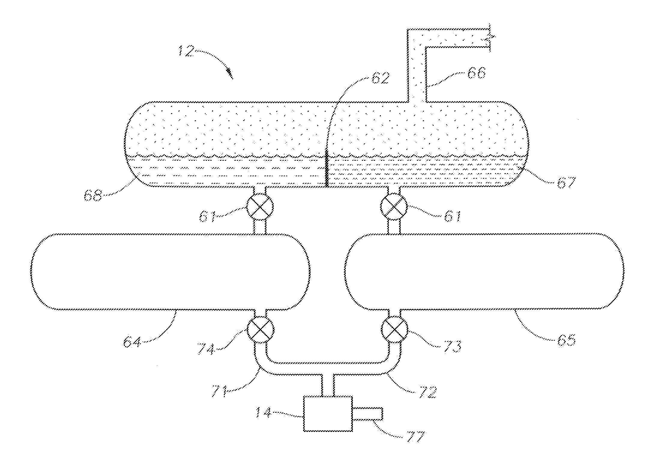
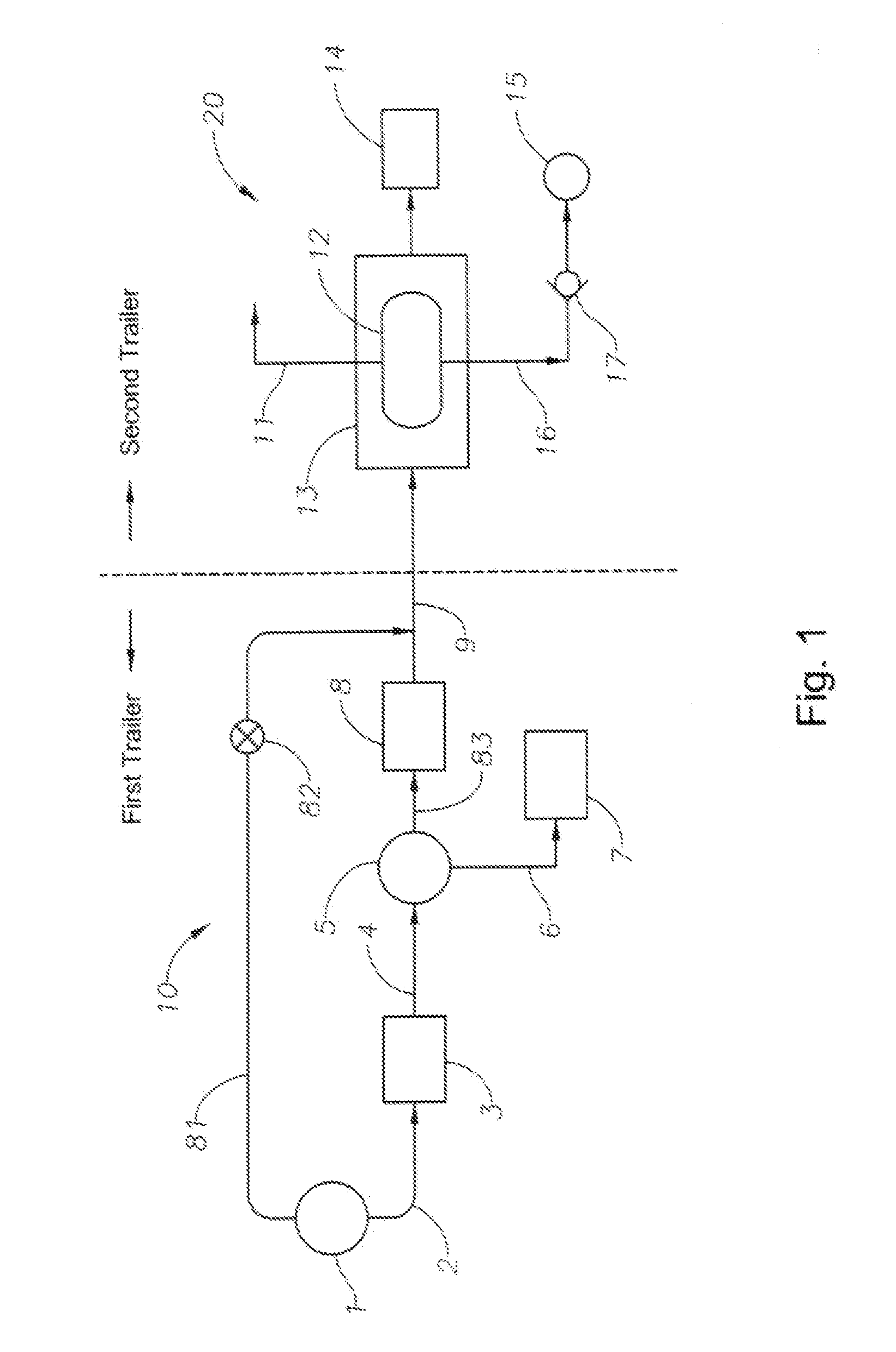
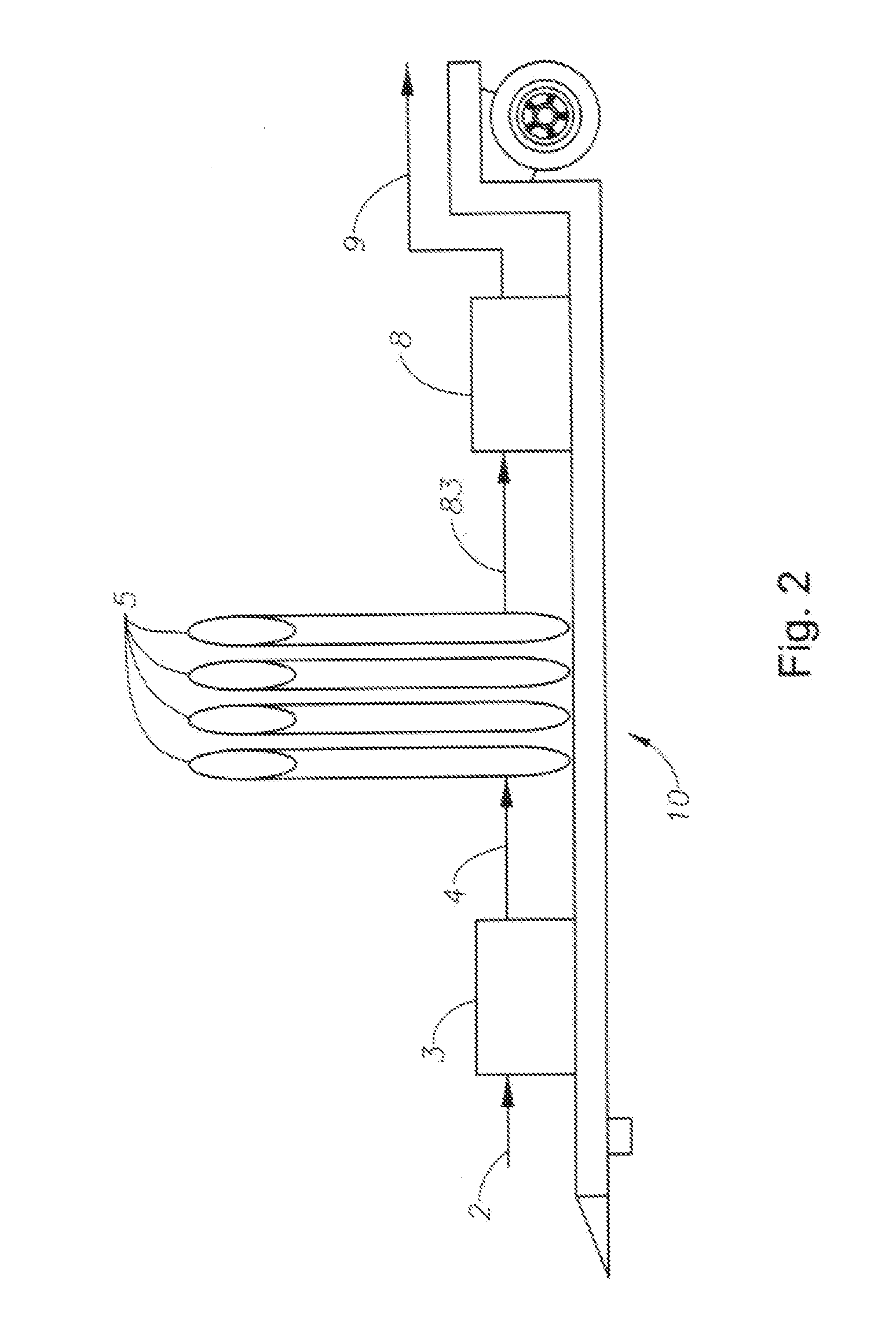
[0013]FIG. 1 depicts an embodiment overall design of the system. Flow back from a well head 1 is directed via conduit 2 to a first trailer 10. Trailer 10 includes a high pressure filter 3 for filtering out relatively large solid particles such as rocks or pieces of equipment that have been broken up during the well completion process. The filter 3 may be formed with high strength metal screens. A second conduit 4 extends to sand separator 5 which is preferably of the type disclosed in copending application Ser. No. 12 / 766,079 field on Apr. 23, 2010, the contents of which is hereby expressly incorporated herein. The sand separator may include one separator unit or a plurality of units as schematically shown at 5 in FIG. 2. A conduit 6 connected to sand separator 5 carries separated sand to a sand tank 7 remote from trailer 10. Another conduit 83 is connected between sand separator 5 and choke manifold 8. A conventional choke manifold 8 is located in conduit 9 to control the pressure ...


PUM

PropertyMeasurementUnit
Pressureaaaaaaaaaa

Abstract

A system and method for processing flow back from an oil or gas well after a fracturing or other well treatment process includes a first trailer having a high pressure filter, a sand separator, and a choke manifold and a second trailer including a gas separator and holding tanks for water and oil. Each trailer may be equipped with a drip or catch pan to confine any leakage of liquid that may occur.

Description

BACKGROUND OF INVENTION[0001]1. Field of the Invention[0002]This invention relates to the handling of flow back which occurs during the cleaning or preparation of oil or gas wells for long term production. The flow back material may include a mixture of water, gas, oil, sand, solid rocks or other solids, completion fluid and drilling mud for example. Various components such as filters, sand separators, chokes, liquid gas separators and tanks along with necessary valves, storage tanks and piping are currently used to process the flow back.[0003]2. Description of Related Art[0004]Currently the materials that are recovered during these flow back operations are considered to have little or no commercial value. In most cases the oil, gas, water and sand are all recovered into a common tank wherein the gas is allowed to vaporize to the atmosphere and the sand settles to the bottom of the tank with the oil and water being left to be disposed of or to be manually skimmed and separated durin...

Claims


Application Information

Patent Timeline
IPC IPC(8): E21B43/00B01D19/00
CPCB01D17/0208B01D19/0042E21B43/34B01D2221/04B01D2221/08B01D21/34E21B43/35
Inventor NOLES, JR., JERRY W.
Owner EXPRESS ENERGY SERVICES OPERATING LP
Why Eureka
Try Eureka