Reception, processing, handling and distribution of hydrocarbons and other fluids

a technology for hydrocarbons and other fluids, which is applied in the direction of liquid handling, container discharging methods, packaged goods types, etc., can solve the problems of large capital investment, large capital and operating costs, and large capital investment, and achieves the reduction of the rate, the effect of reducing the offload time of carriers, and substantial savings in capital and operating costs

Inactive Publication Date: 2008-01-29
MPEH LLC
View PDF15 Cites 39 Cited by
  • Summary
  • Abstract
  • Description
  • Claims
  • Application Information

AI Technical Summary

Benefits of technology

[0008]The method and system of this invention exhibits certain unique features that distinguish them from conventional technologies for the transportation, regasification, storage and distribution of hydrocarbons. For example, like in the case of conventional LNG terminals, the LNG that is handled by the method and system of this invention may be offloaded from a carrier ship into a surface tank. However, unlike the case of conventional LNG terminals, the surface holding tank of the method and system of this invention is used for certain unique purposes, and is not used for conventional bulk storage. The surface holding tank of the method and system of this invention is used to minimize carrier offload time, afford continuous operation of the energy hub vaporization stage and maintain the temperature of the vaporizer system at the desired level. The surface holding tank is a key component in economically offloading a carrier ship within a short time frame, and its use translates into substantial savings in the capital and operating costs associated with the vaporization equipment that is required to rapidly offload the ship. Once the ship is offloaded, the vaporization equipment will operate at a reduced rate utilizing the LNG from the tank to continue operations. Unlike the technologies used in standard LNG terminals, where the removal of the NGL takes place downstream from the vaporization step, the method and system of this invention allow the processing of the LNG for removing NGL in the liquid phase before entering the vaporizers. In this fashion, the gas may be stored in a salt cavern or subsea reservoir, if desired, and then sent to market distribution with minimal or no further processing. (Such processing is carried out by means of well known technologies.) The removal of the NGL can always take place downstream from the vaporization step and from the storage cavern if desired or required by the business distribution demand or by any other process operating reason. Unique to the offshore version of the energy hub concept is the benefit of being able to have salt domes and caverns located directly underneath, or in the immediate vicinity of, the offshore receiving platform or facility on which the surface holding tank and the vaporization equipment are installed. In addition, there is potential for some caverns to utilize oil or other liquids to displace gas from the caverns. Cavern storage allows more rapid offloading of carrier-regassed LNG and CNG offloaded from vessels.

Problems solved by technology

When cryogenic fluids such as LNG are processed at maritime and land-base terminals, the processing always entails large capital investments, which are required by the need to provide expensive cryogenic storage tanks and vaporization equipment.
Furthermore, demurrage and other charges associated with loading and offloading operations to and from the terminals burden the processing with additional costs.
The offloading, handling and distribution of crude oil, processed oil, compressed natural gas, natural gas liquids, liquefied petroleum gas, petrochemicals and so-called gas-to-liquid products, as well as many other fluids, are also burdened with large capital investments and demurrage and other charges associated with the loading and offloading operations.
While the technologies described in these patents serve to address a number of individual product processing situations, none of them addresses the reception, processing, handling and distribution of a combination of these products from a central location under conditions that minimize the capital investments and operating costs required to carry out such reception, processing, handling and distribution operations.

Method used


Image

  • Reception, processing, handling and distribution of hydrocarbons and other fluids
  • Reception, processing, handling and distribution of hydrocarbons and other fluids
  • Reception, processing, handling and distribution of hydrocarbons and other fluids

Examples


Embodiment Construction

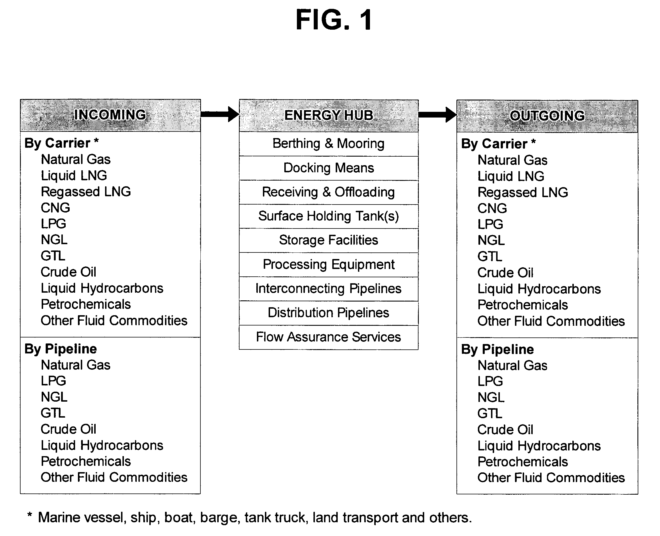
[0014]Referring to FIG. 1, the variety of fluids that the energy hub facility of this invention is able to receive, process, store and / or deliver is shown on the left side of the block labeled “Energy Hub” under the heading “Incoming”. As shown on FIG. 1, these fluids may arrive at the energy hub by carrier ships, boats, barges, tanker trucks, land transport and / or pipelines, and include natural gas, liquefied natural gas (LNG), regassed LNG, compressed natural gas (CNG), liquefied petroleum gas (LPG), natural gas liquids (NGL), gas-to-liquid products (GTL), crude oil (with or without mixed gas), liquid hydrocarbons, petrochemicals, and other fluid commodities, such as mineral and vegetable oils, NaOH, NaCl clarifiers, ethylenebenzene, benzene, raffinate and other liquid and gaseous chemicals. The fluids are handled and processed at the energy hub, which is equipped with means for berthing, mooring and docking ships, boats, barges, trucks and / or land transport, receiving and offload...


PUM

PropertyMeasurementUnit
pressureaaaaaaaaaa
temperatureaaaaaaaaaa
pressureaaaaaaaaaa

Abstract

An integrated energy hub facility capable of bringing together all aspects of hydrocarbon and other fluid product movement under controlled conditions applicable to the reception, storage, processing, collection and transmission downstream is provided. Input to the energy hub includes natural gas and crude from a pipeline or a carrier, LNG from a carrier, CNG from a carrier, and carrier-regassed LNG, as well as other products from a pipeline or a carrier. Storage can be above surface, in salt caverns or in subterranean formations and cavities, and include petroleum crude, natural gas, LPG, NGL, GTL and other fluids. Transmission downstream may be carried out by a vessel or other type of carrier and / or by means of a pipeline system. Cryogenic fluids are offloaded and sent to the energy hub surface holding tank, then pumped to the energy hub vaporizers and sent to underground storage and / or distribution.

Description

[0001]This application is a non-provisional application for patent entitled to a filing date and claiming the benefit of earlier-filed Provisional Application for Patent No. 60 / 499,715, filed on Sep. 4, 2003 under 37 CFR 1.53 (c).FIELD OF THE INVENTION[0002]This invention relates to the reception, processing, handling and distribution of hydrocarbons and other fluids. Particularly, this invention relates to a method and system for transporting, offloading, handling, regasifying, storing and distributing hydrocarbons and other fluids. More particularly, the invention relates to a method and system for the offloading, regasification, storage and distribution of liquefied natural gas and other hydrocarbons at a central location using limited volume of surface holding tank capacity and conventional vaporization technology. Specifically, the invention relates to a novel technique for combining existing proven components found in liquefied natural gas terminals and offshore loading system...

Claims


Application Information

Patent Timeline
Patent Type & Authority Patents(United States)
IPC IPC(8): B65B1/04F17CF17C7/04F17C9/02
CPCF17C7/04F17C2221/033F17C2265/05F17C2270/0163F17C2221/035F17C2223/0153F17C2223/0161F17C2223/033F17C2225/0123F17C2225/036F17C2227/0302F17C2227/0393F17C2250/01F17C2270/0105F17C2270/0123F17C2270/0152
Inventor LANDRY, DAVID CHARLESMADUELL, ROGER JACQUES
Owner MPEH LLC
Why Eureka
Try Eureka