Plastic dual-in-line packaging (PDIP) having enhanced heat dissipation

Inactive Publication Date: 2005-05-26
TEXAS INSTR INC
View PDF1 Cites 10 Cited by
  • Summary
  • Abstract
  • Description
  • Claims
  • Application Information

AI Technical Summary

Benefits of technology

[0004] In accordance with the present invention, a plastic dual-in-line packaging (PDIP) having enhanced heat dissipation. According to one embodiment, an electronic device comprising a plastic dual-in-line packaging (PDIP) package

Problems solved by technology

In addition, PDIP packages are relatively large, and thus are often used where small size is not a high priority.
As a result, the

Method used


Image

  • Plastic dual-in-line packaging (PDIP) having enhanced heat dissipation
  • Plastic dual-in-line packaging (PDIP) having enhanced heat dissipation
  • Plastic dual-in-line packaging (PDIP) having enhanced heat dissipation

Examples


Example

DETAILED DESCRIPTION OF THE DRAWINGS

[0017] Example embodiments of the present invention and their advantages are best understood by referring now to FIGS. 1 through 5 of the drawings, in which like numerals refer to like parts.

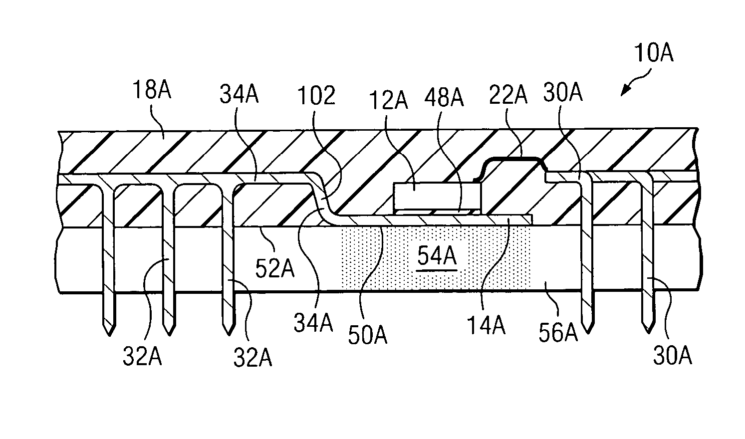
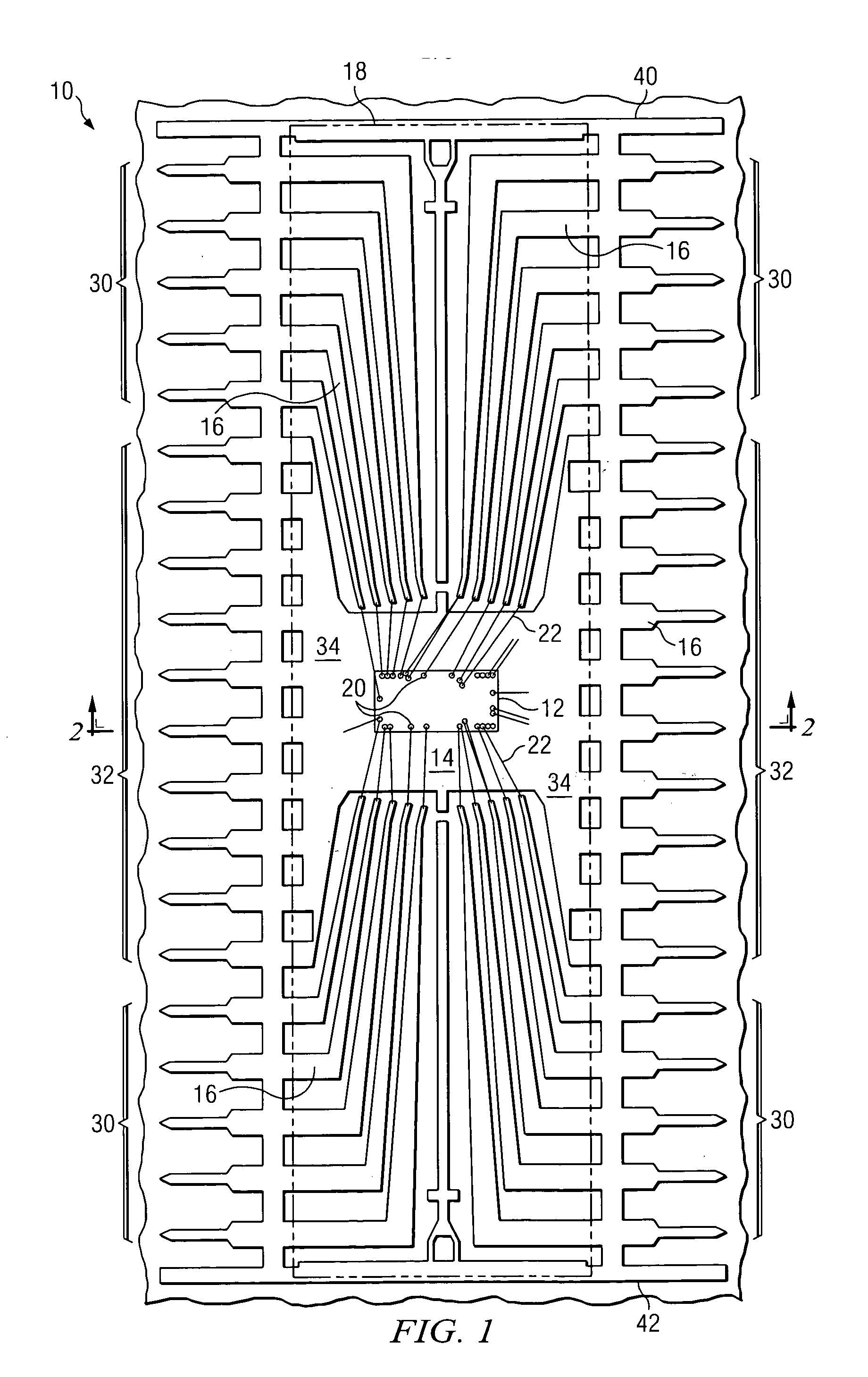
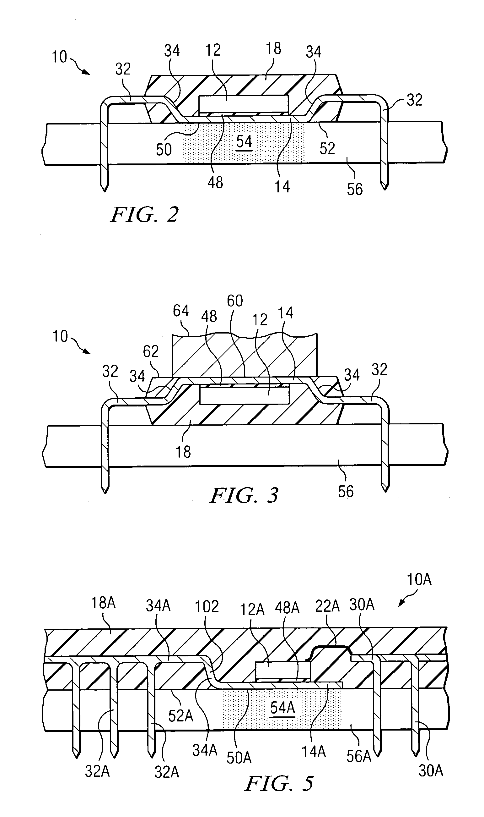
[0018]FIG. 1 illustrates a top view of a plastic dual-in-line packaging (PDIP) package 10 in accordance with one embodiment of the present invention. PDIP package 10 includes a die 12 coupled to a die attach pad 14, a plurality of conductive leads 16, and a mold structure 18.

[0019] Die 12, which may be called a chip or microchip, may be any type of semiconductor device, such as an ASIC, a CPLD, a Flash device, an FPGA, a microcontroller, or an SOC, for example. Die 12 includes a number of contact points 20 to which conductive wires 22 are attached to create connections with various leads 16. Conductive wires 22 are formed from one or more suitable conductive materials, such as copper, gold or aluminum, for example. Conductive wires 22 may be relatively thin...


PUM


Abstract

According to one embodiment, an electronic device comprising a plastic dual-in-line packaging (PDIP) package structure is provided. The PDIP package structure includes a mold structure, a die disposed within the mold structure, and a die attach pad coupled to the die. The die attach pad has a first surface exposed from the mold structure.

Description

TECHNICAL FIELD OF THE INVENTION [0001] This invention relates in general to die packaging, and, more particularly, to a plastic dual-in-line packaging (PDIP) having enhanced heat dissipation. BACKGROUND OF THE INVENTION [0002] Plastic dual-in-line packaging (PDIP) is a typical die or chip package using pin-through-hole (PTH) technology. PDIP packages include various numbers of pins, or leads. For example, common PDIP packages include 28-pin PDIPs and 40-pin PDIPs. PDIP packages are widely used for low cost and hand-inserting applications. In addition, PDIP packages are relatively large, and thus are often used where small size is not a high priority. PDIP packages broad application includes consumer products, automotive devices, logic, memory ICs, microcontrollers, logic and power ICs, video controllers commercial electronics and telecommunications. [0003] As dies (or chips) have become smaller and more dense, the heat generated during the operation of such dies has increased accor...

Claims


Application Information

Patent Timeline
IPC IPC(8): H01L23/495H01L23/34
CPCH01L23/49551H01L2224/32245H01L2224/48095H01L2224/48247H01L2224/48472H01L2224/49171H01L2924/01079H01L2924/1433H01L23/49568H01L2224/73265H01L24/49H01L24/48H01L2924/00014H01L2924/00H01L2924/181H01L2224/45015H01L2224/45124H01L2224/45147H01L2224/45144H01L24/45H01L2924/00012H01L2924/2075H01L23/34
Inventor COYLE, ANTHONY L.
Owner TEXAS INSTR INC
Why Eureka
Try Eureka