Electrical connector

Active Publication Date: 2020-09-24
FOXCONN (KUNSHAN) COMPUTER CONNECTOR CO LTD +1
View PDF0 Cites 2 Cited by
  • Summary
  • Abstract
  • Description
  • Claims
  • Application Information

AI Technical Summary

Benefits of technology

[0004]To achieve the above object, an electrical connector includes an insulative housing having opposite mating port and mounting port. Plural pairs of contacts are retained in the housing. Each pair of contacts has a first contact blade and a second contact blade. Each of the first contact blade and the second contact blade includes a main body, a contacting section extending into the

Problems solved by technology

Anyhow, because the power contact has a U-shaped structure for lin

Method used


Image

  • Electrical connector
  • Electrical connector
  • Electrical connector

Examples


Example

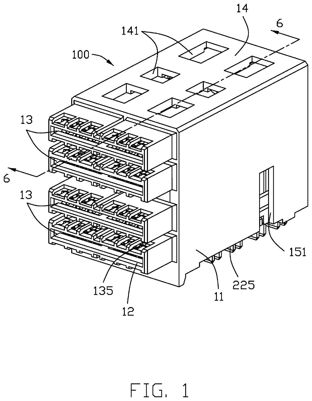
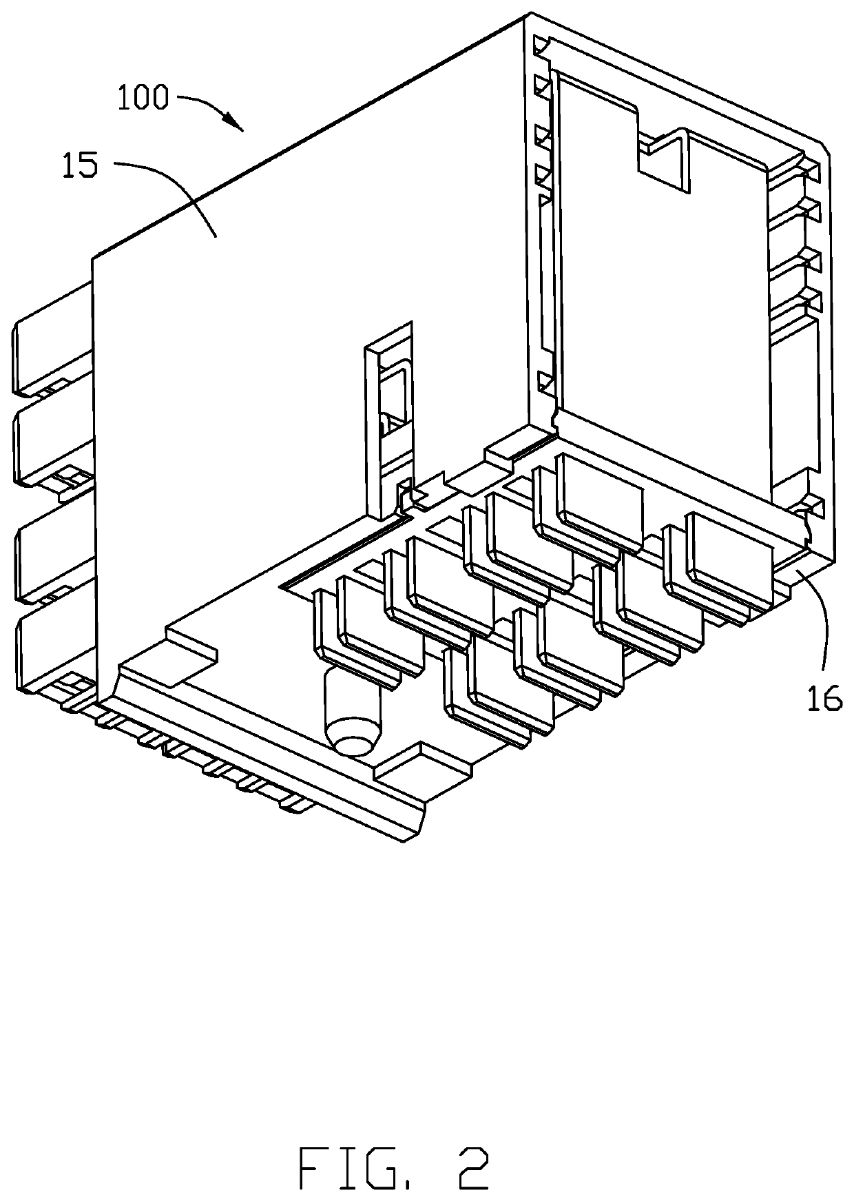
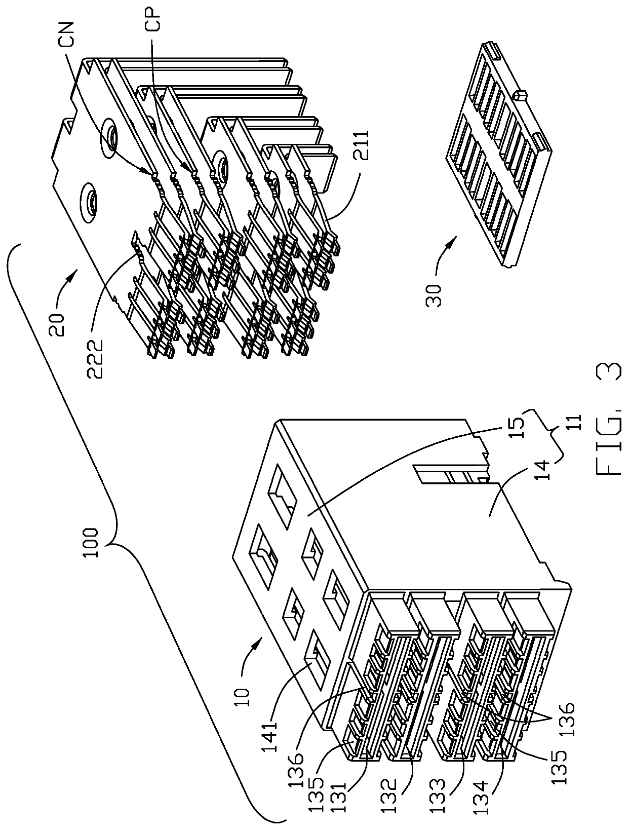
[0013]Referring to FIGS. 1-7, an electrical connector 100 includes an insulative housing 10, plural pairs of contacts 20 retained in the housing 10, and a spacer 30 retaining the mounting legs of the contacts 20. The housing 10 includes a main portion 11, a mating port 12 forwardly extending from the main portion 11, and a mounting port 16 below the main portion 11. The mating port 12 forms four mating cavities 13 including a first mating cavity 131, a second mating cavity 132, a third mating cavity 133 and a fourth mating cavity 134. A distance between the first mating cavity 131 and the second mating cavity 132 is same with that between the third mating cavity 133 and the fourth mating cavity 134. The first mating cavity 131 and the second mating cavity 132 commonly form a first mating part wherein the first mating cavity 131 is for negative connection while the second mating cavity 132 is for positive connection. Similarly, the third mating cavity 133 and the fourth mating cavity...


PUM


Abstract

An electrical connector includes an insulative housing having opposite mating port and mounting port. Plural pairs of contacts are retained in the housing. Each pair of contacts has a first contact blade and a second contact blade. Each of the first contact blade and the second contact blade includes a main body, a contacting section extending into the mating port, and a mounting leg of the main body disposed in the mounting port. Each of the main body of the first contact blade and the main body of the second contact blade forms an embossment abutting against each other so as to electrically unify both the first contact blade and the second contact blade without blocking the space therebetween for enhancing heat dissipation thereof.

Description

BACKGROUND OF THE INVENTION1. Field of the Invention[0001]The invention relates to the electrical connector, and particularly to an electrical connector with good heat dissipation.2. Description of Related Arts[0002]China Patent No. CN203911048U discloses an electrical connector including an insulative housing with at least one set of power contacts and at least one set of signal contacts. Anyhow, because the power contact has a U-shaped structure for linking the opposite spring fingers, the heat dissipation is inferior.[0003]Hence, an electrical connector with the good heat dissipation effect, is desired.SUMMARY OF THE INVENTION[0004]To achieve the above object, an electrical connector includes an insulative housing having opposite mating port and mounting port. Plural pairs of contacts are retained in the housing. Each pair of contacts has a first contact blade and a second contact blade. Each of the first contact blade and the second contact blade includes a main body, a contacti...

Claims


Application Information

Patent Timeline
IPC IPC(8): H01R13/428H01R13/436
CPCH01R13/428H01R13/4361H01R13/02H01R13/193H01R12/7088H01R12/724H01R13/115H01R13/41H01R13/502
Inventor LIANG, YUN-KUISHU, FANG-HUAQI, YUNSHAO, JIANCHEN, ZHI-JIANBU, XUE-WU
Owner FOXCONN (KUNSHAN) COMPUTER CONNECTOR CO LTD
Why Eureka
Try Eureka