
Electric motor

a technology of electric motors and motors, applied in the direction of magnetic circuit rotating parts, electric devices, magnetic circuit shapes/forms/construction, etc., can solve the problem of increasing torque without significantly increasing power, and achieve the effect of reducing longitudinal dimensions and increasing torqu

Inactive Publication Date: 2005-05-26
ULTRA MOTOR CO LTD
View PDF8 Cites 13 Cited by
  • Summary
  • Abstract
  • Description
  • Claims
  • Application Information

AI Technical Summary

Benefits of technology

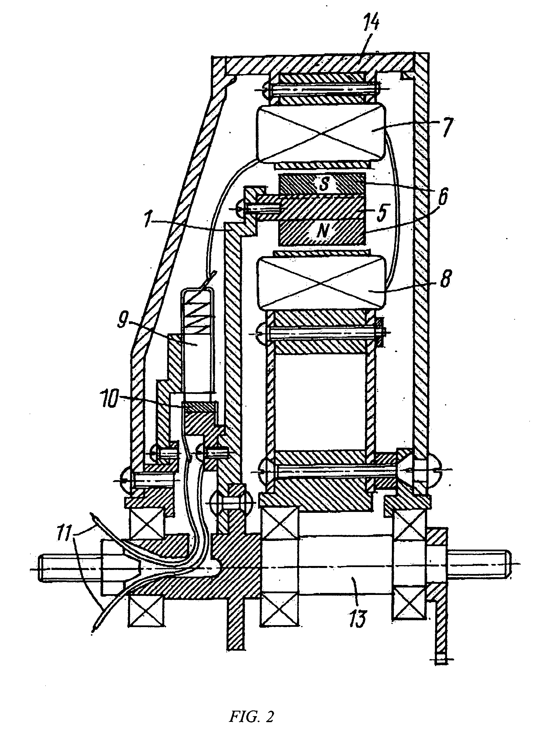
[0013] The present invention applies the same principle, but by a different arrangement, which gives the electric motor certain advantages both in its consumer characteristics (such as a further increase of torque due to reduction of magnetic resistance), and also because of the reduction in longitudinal dimensions of the motor, which is particularly important for motors of the “motor-wheel” type.
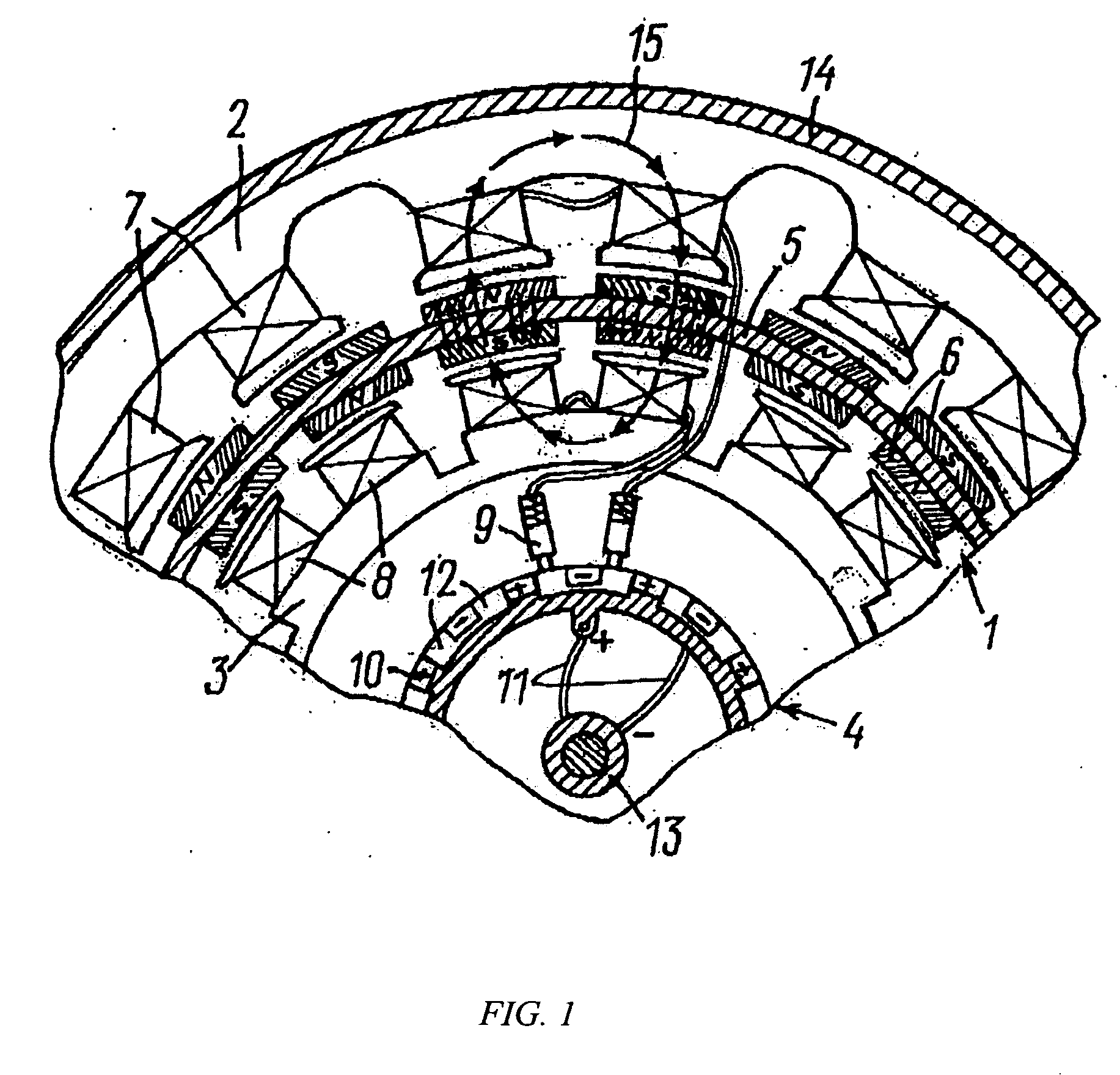
[0021] Unlike the aforementioned patent, the electric motor described in the present patent application can achieve this by having the two rows of permanent magnets located not on the same side, but on opposite sides of the annular magnetic conductor, opposite each other; and the adjacent magnets set opposite each other are of opposite polarity.

Problems solved by technology

One of the main problems facing developers of electric motors of this type is to increase torque without significantly increasing the power (in particular, the voltage) of the supply source.

Method used


Image

  • Electric motor
  • Electric motor
  • Electric motor

Examples


Embodiment Construction

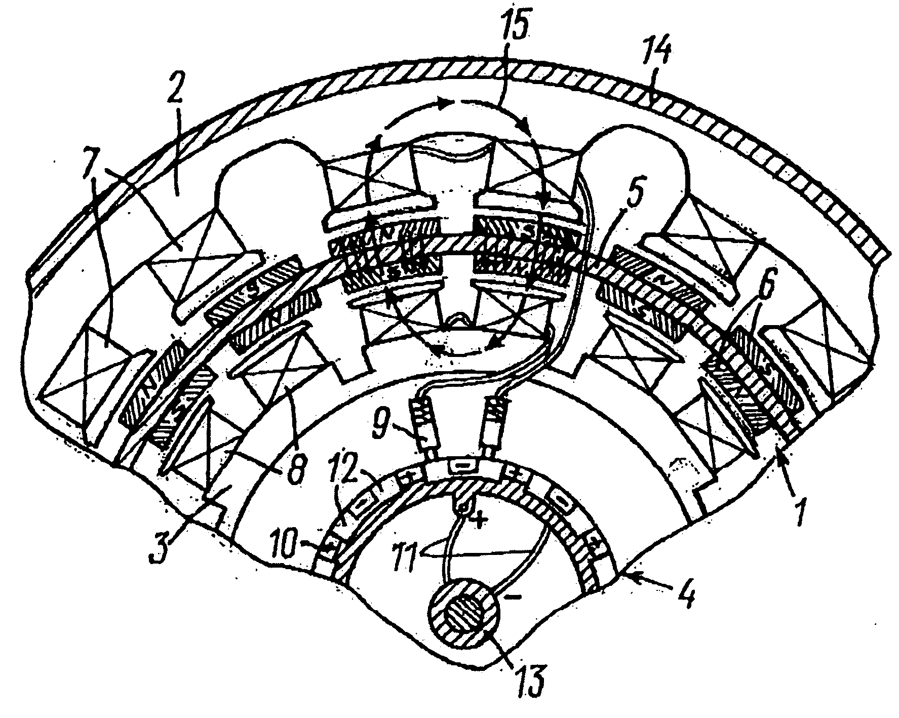
[0028] The electric motor consists of a stator (1), external (2) and internal (3) sections of the rotor, and a distributor (collector) (4).

[0029] For its part, the stator consists of an annular magnetic conductor (5) and permanent magnets (6) placed on it on both sides, opposite each other. The magnets have alternating polarity relative to the adjacent electromagnets in the row (located on the same side of the magnetic conductor) and opposite polarity of the magnets on the two sides of the magnetic conductor opposite each other. The external (2) and internal (3) sections of the rotor carry electromagnets (7 and 8 respectively). These electromagnets face each other, and each facing pair of electromagnets is located co-axially, in the same diametrical plane. Adjacent electromagnets in the rotor sections are connected in pairs to the current collectors (9). These can be displaced round the distributor for possible adjustment of the electric motor.

[0030] The cylindrical collector (4) ...


PUM


Abstract

An electric motor intended for driving transport vehicles without a reduction gear is described. The electric motor can have an annular magnetic conductor of the stator with permanent magnets located on opposite sides of the magnetic conductor, and a two-section rotor, one section of which goes round the stator, while the other is inside it. The electric motor provides greater torque.

Description

CROSS-REFERENCE TO RELATED APPLICATIONS [0001] Incorporated herein by reference is my Russian Patent Application No. 2003126931, filed 4 Sep. 2003. [0002] Incorporated herein by reference is my U.S. Provisional Patent Application No. 60 / 513,911, filed 23 Oct. 2003. [0003] Priority is hereby claimed to Russian Patent Application No. 2003126931, filed 4 Sep. 2003. [0004] Priority is hereby claimed to U.S. Provisional Patent Application No. 60 / 513,911, filed 23 Oct. 2003. STATEMENT REGARDING FEDERALLY SPONSORED RESEARCH OR DEVELOPMENT [0005] Not applicable REFERENCE TO A “MICROFICHE APPENDIX”[0006] Not applicable BACKGROUND OF THE INVENTION [0007] 1. Field of the Invention [0008] The invention relates to electric motors, primarily for vehicles, in the form of motor-wheels, and is intended for use in electrically propelled bicycles, wheelchairs, workshop machinery, electric cars and other vehicles and machines. [0009] 2. General Background of the Invention [0010] Collector motor-wheels ...

Claims


Application Information

Patent Timeline
Patent Type & Authority Applications(United States)
IPC IPC(8): B60K7/00H02K16/02H02K25/00
CPCB60K7/0007B60K2007/0038H02K25/00H02K16/02B60K2007/0092B60L50/20B60L2200/12B60L2200/34B60L2200/40B60L2220/44B60L2220/50B60L2240/423Y02T10/64
Inventor SHKONDIN, VASILY VASILIEVICH
Owner ULTRA MOTOR CO LTD
Learn More