Intravascular filter and method

a filter and filtering technology, applied in the field of minimally invasive percutaneous procedures, can solve the problems of less fragile plaque and thrombosis of vein grafts, and the incidence of embolism due to the breaking off of plaque or thrombosis substantially greater than that found in native arteries

Inactive Publication Date: 2005-05-26
BOSTON SCI SCIMED INC
View PDF4 Cites 47 Cited by
  • Summary
  • Abstract
  • Description
  • Claims
  • Application Information

AI Technical Summary

Benefits of technology

[0012] The elongate shaft of the filter assembly can have an elongate wire lumen running through its length. In such a configuration, the catheter can be considered an over-the-wire catheter. The catheter can be converted to a single operator exchange catheter by dividing the shaft into two or more elongate segments and coupling the segments together. The length of the segments should be such that they can be uncoupled or coupled as they are being withdrawn or advanced over the wire. The coupling could include a bayonet fastener or a threaded fastener for example. As an alternative to the coupling, the catheter can be configured for a single operator exchange by providing a telescoping or collapsible portion. The collapsible portion can include a member which can have a braided portion. In an alternate embodiment, the catheter can include longitudinal slits for removal of the catheter from the wire.

Problems solved by technology

When these procedures are performed on saphenous vein grafts, however, the incidence of embolism due to the breaking off of plaque or thrombus from the vein graft is substantially greater than from native arteries.
In addition, the plaque and thrombus of vein grafts is somewhat more fragile than that found in native arteries.

Method used


Image

  • Intravascular filter and method
  • Intravascular filter and method
  • Intravascular filter and method

Examples


Embodiment Construction

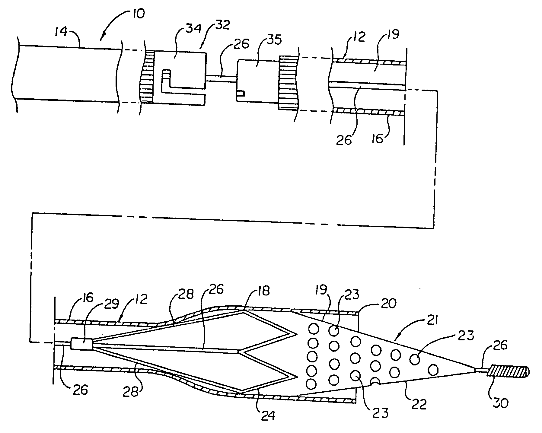
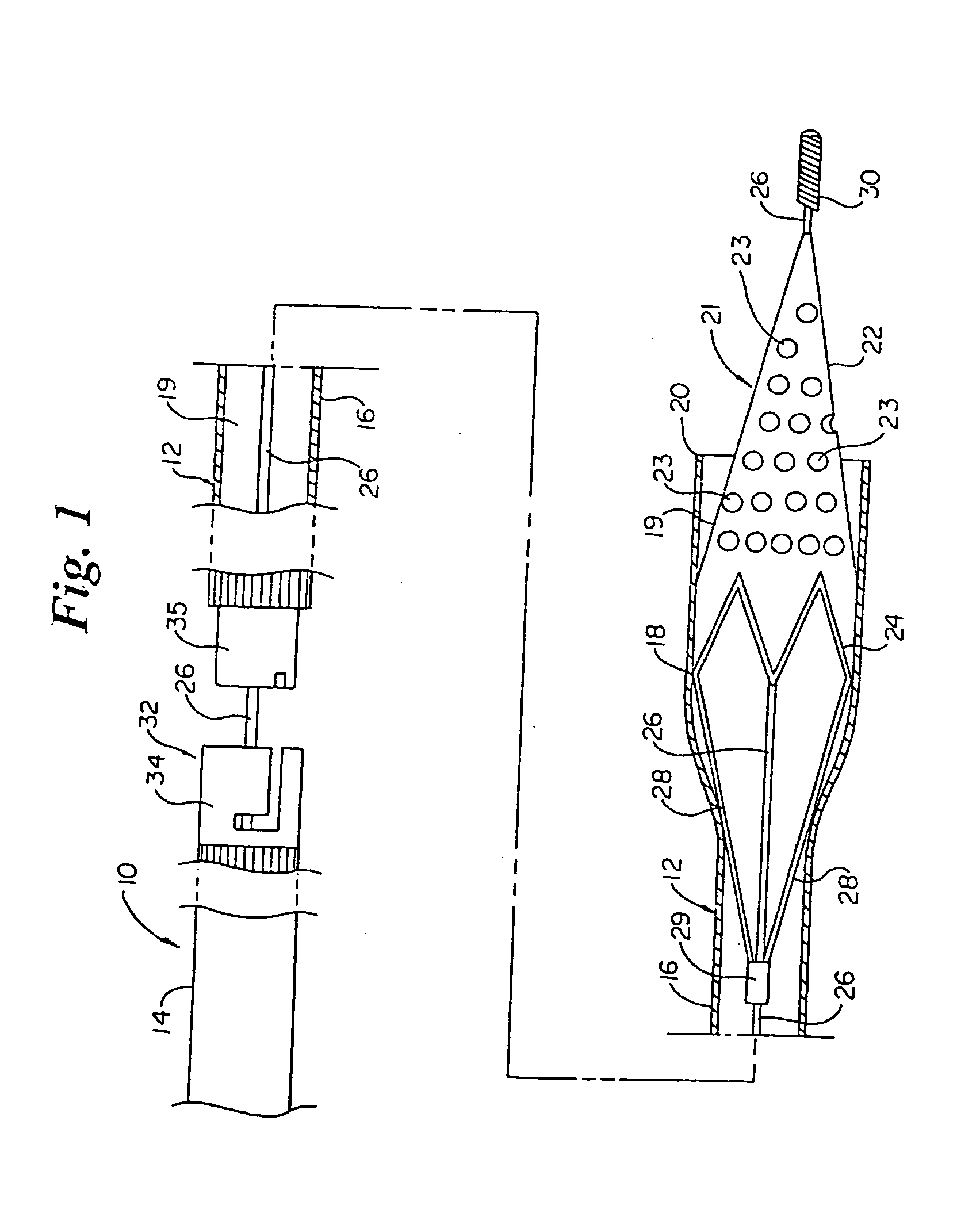
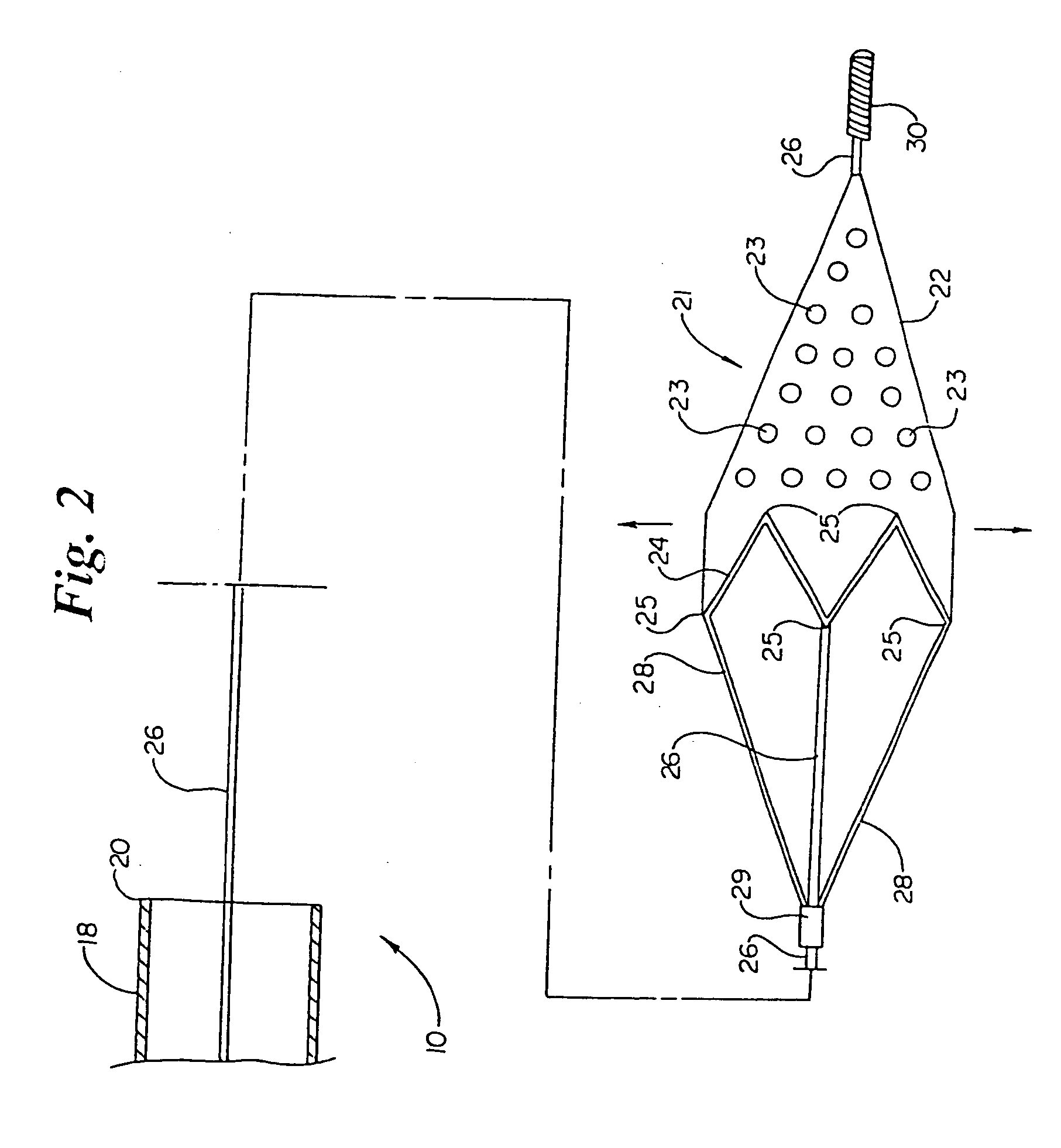
[0040] Referring now to the drawings wherein like reference numerals refer to like elements throughout the several views, FIG. 1 is a partial cross sectional, side view of a filter assembly 10 in accordance with the present invention. Filter assembly 10 includes a delivery catheter 12. Delivery catheter 12 can include a proximal section 14 coupled to a distal section 16. Disposed at the distal end of catheter 12 is a filter housing 18. Filter housing 18 has a distal end 20. As known to those skilled in the art, a manifold having guide wire and side ports can be disposed at the proximal end of catheter 12.

[0041] Catheter 12 preferably defines a lumen 19 extending therethrough. In the region of housing 18, lumen 19 preferably has a diameter of between 2 F to 5 F and more preferably, between 3 F to 4 F and most preferably, about 3 F. The diameter of lumen 19 in shaft sections 14 and 16 is preferably between 2 F and 5 F and most preferably, about 2 F.

[0042] The length of the delivery ...


PUM


Abstract

A filter disposed at the distal end of an elongate guidewire. Catheters are provided for delivering the filter to, and retrieving the filter from, a treatment site. The catheters can be over-the-wire or single operator exchange. The catheters include a housing for receiving the filter therein. The housing has an atraumatic distal end.

Description

RELATED APPLICATIONS [0001] This application is related to U.S. patent application Ser. No. 08 / 813,794, entitled “Distal Protection Device” and U.S. patent application Ser. No. 09 / 035,740, entitled “Distal Protection Device and Method”, both of which are incorporated herein by reference.BACKGROUND OF THE INVENTION [0002] The present invention relates to the field of minimally invasive, percutaneous procedures such as angioplasty. In particular, the invention relates to a distal filter for use during such a procedure. [0003] Angioplasty, atherectomy and stent placement, among other procedures, have become well accepted for treatment of coronary lesions. These procedures are often performed as an alternative to coronary bypass. It is also possible, however, that a saphenous vein graft, which is used to bypass coronary lesions, may itself develop a lesion. These lesions may also be treated by minimally invasive procedures such as angioplasty, atherectomy and / or stent placement. [0004] ...

Claims


Application Information

Patent Timeline
Patent Type & Authority Applications(United States)
IPC IPC(8): A61F2/00A61F2/01
CPCA61F2/01A61F2/013A61F2002/011A61F2230/0067A61F2250/0098A61F2002/018A61F2230/0006A61F2250/0023A61F2/0108A61F2/011
Inventor DANIEL, JOHNLOWE, BRIAN J.CASSELL, ROBERTSLAKER, BRADLEY F.ARNOLD, JOHN E. JR.BROOME, THOMAS E.
Owner BOSTON SCI SCIMED INC
Why Eureka
Try Eureka