Area coverage with an autonomous robot

a robot and autonomous technology, applied in the field of autonomous robots, can solve the problems of time-consuming and error-prone creation of the map b>28/b> of the shape of the area to be covered

Inactive Publication Date: 2005-05-26
MTD PRODUCTS
View PDF21 Cites 87 Cited by
  • Summary
  • Abstract
  • Description
  • Claims
  • Application Information

AI Technical Summary

Problems solved by technology

However, it will be appreciated that creating the map 28 of the shape of the area to be covered is time consuming.
Due to the inaccuracies of the compass 26 and odometer 24, it is also typically error prone.

Method used


Image

  • Area coverage with an autonomous robot
  • Area coverage with an autonomous robot
  • Area coverage with an autonomous robot

Examples


Embodiment Construction

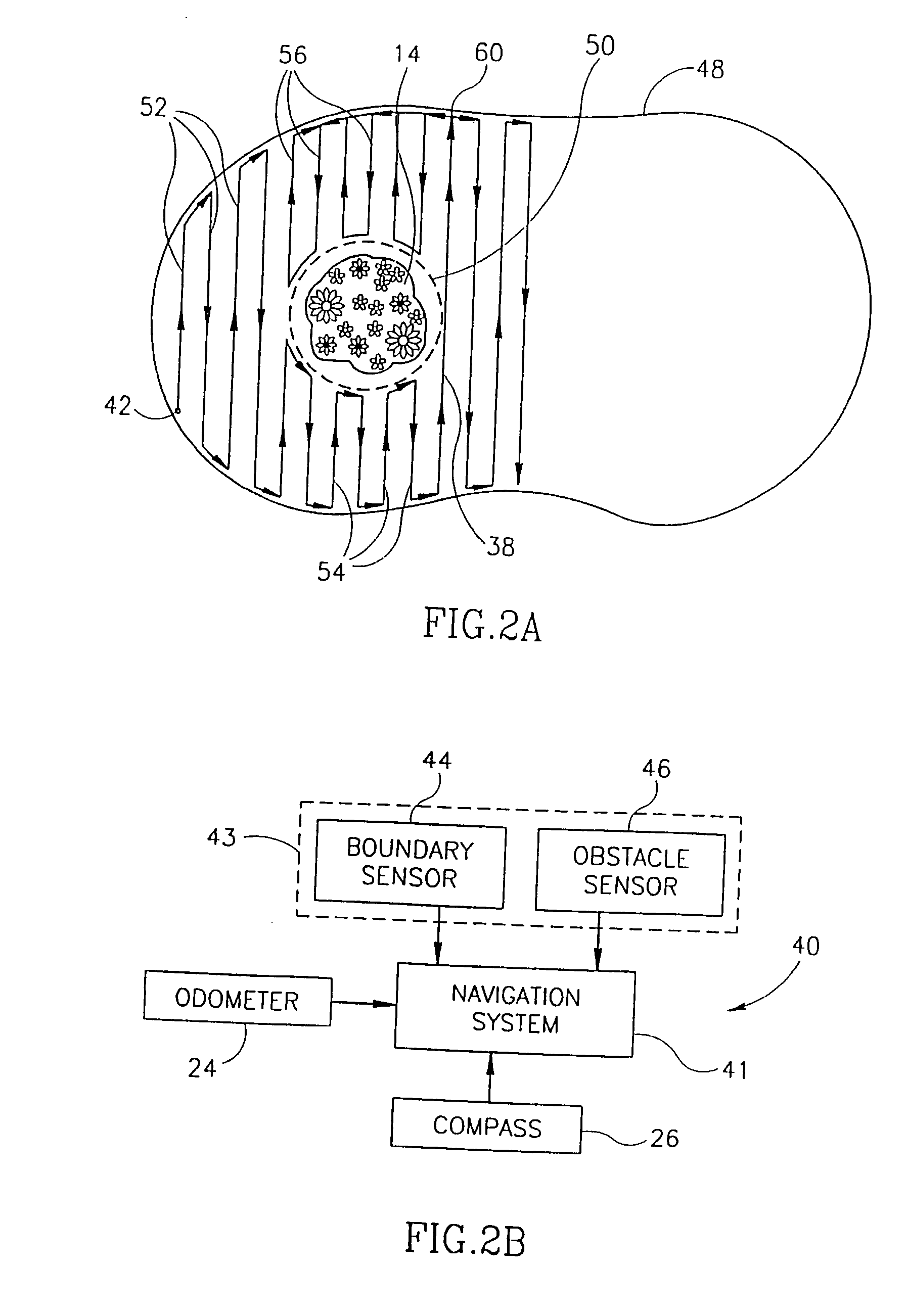
[0029] Reference is now made to FIGS. 2A and 20 which illustrate the movement of a robot 40 of the present invention and the elements of the robot, respectively. Similar reference numerals refer to similar elements.

[0030] In accordance with a preferred embodiment of the present invention, robot 40 does not create a map of the area to be covered. Instead, it systematically scans within the area, moving in a straight direction from one boundary marker to the next. To do so, it must initially be placed relatively close to one extreme edge of the boundary, for example at starting point 42, and faced in the desired direction of scanning.

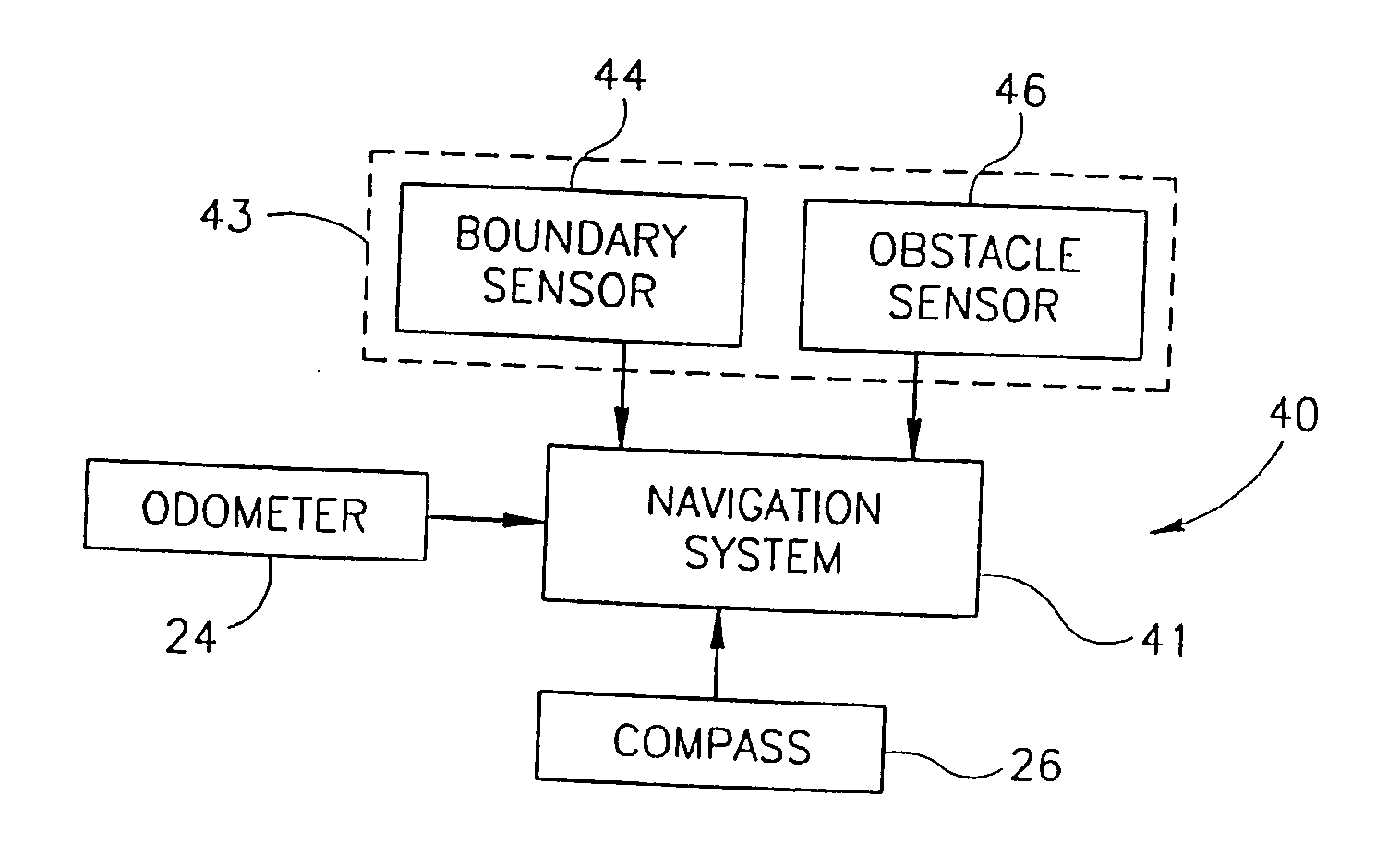
[0031] As can be seen in FIG. 2B, the robot 40 utilizes the odometer 24 and compass 26 but comprises a navigation system 41 and a sensor system 43, shown as two sensors 44 and 46, for separately sensing the boundary and the obstacles, respectively. Accordingly, there can be two different types of markers, boundary markers 48 and obstacle markers 50. The...


PUM


Abstract

There is therefore provided, in accordance with a preferred embodiment of the present invention, a robotic system for systematically moving about an area to be covered. The system includes at least one boundary marker (48) located along the outer edge of the area to be covered, a robot (40) with a navigation system (41) navigates the robot (40) in generally straight, parallel lines from an initial location and turns the robot (40) when the robot (40) encounters one of the boundary markers (48), thereby to systematically move about the are to be covered. The sensor unit (43) senses proximity to one of the at least one boundary marker (48).

Description

FIELD OF THE INVENTION [0001] The present invention relates to autonomous robots generally and to autonomous robots which move through an area in particular. BACKGROUND OF THE INVENTION [0002] Autonomous robots are known in the art and have been implemented as household appliances, such as a lawnmower or a vacuum cleaner. These household appliances operate by moving about an area to be processed such that the entire area is covered by the end of the operation. [0003] Reference is now made to FIGS. 1A and 1B which illustrate the operation of one exemplary autonomous robot, described in U.S. patent application Ser. No. b 08 / 554,691, filed 7 Nov. 1995 and assigned to the common assignees of the present invention. U.S. patent application Ser. No. 08 / 554,691 is incorporated herein by reference. FIG. 1A illustrates the area in which the robot 10 operates and FIG. 1B illustrates the elements, in block diagram form, of robot 10. [0004] The autonomous robot 10 operates within an area marked ...

Claims


Application Information

Patent Timeline
Patent Type & Authority Applications(United States)
IPC IPC(8): G05D1/02
CPCG05D1/0219G05D1/0227G05D1/0236G05D1/0261A01D34/008G05D1/027G05D1/0272G05D1/0274G05D2201/0208G05D1/0265
Inventor PELESS, EHUDABRAMSON, SHAIFRIEDMAN, RONENPELEG, ILAN
Owner MTD PRODUCTS
Why Eureka
Try Eureka