
Electronically-controlled suspension apparatus and damping force control method

a technology of suspension apparatus and control method, which is applied in the direction of bicycle equipment, instruments, transportation and packaging, etc., can solve the problems of ride comfort deterioration and ride comfort deterioration, and achieve the effect of improving ride comfort and steering stability of the vehicl

Inactive Publication Date: 2005-05-26
HL MANDO CORP
View PDF0 Cites 39 Cited by
  • Summary
  • Abstract
  • Description
  • Claims
  • Application Information

AI Technical Summary

Benefits of technology

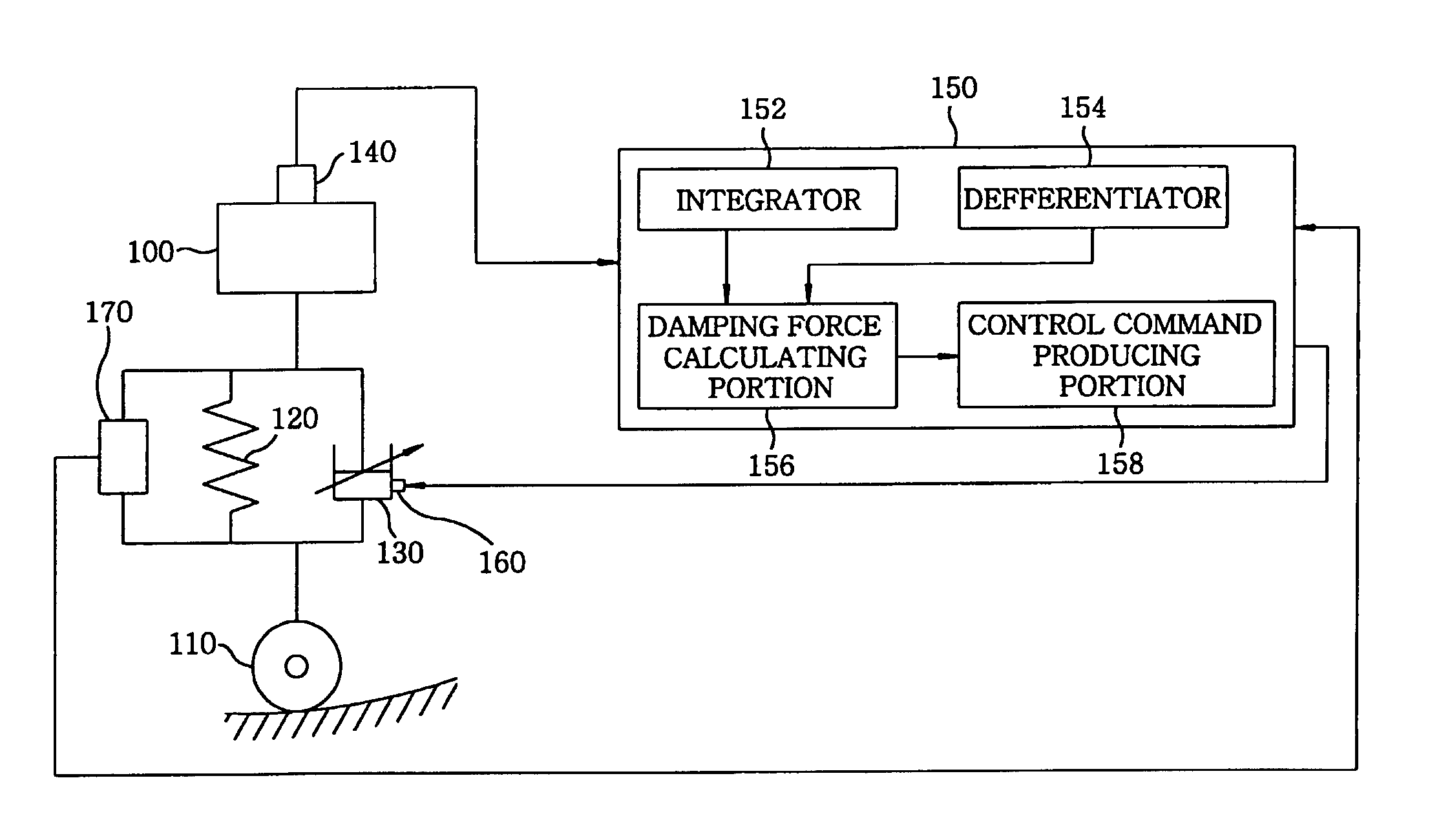
[0008] It is, therefore, an object of the present invention is to provide an electronically-controlled suspension apparatus and damping force control method, which is capable of improving ride comfort and steering stability of a vehicle by using not only a vertical speed of a vehicle body but also a damper speed of a variable damper.

Problems solved by technology

And if the magnitude (or absolute value) of the damper speed is increased, the damping force is abruptly changed, resulting in ride comfort deterioration.
Further, if a phase of the damper speed is opposed to that of a target damping force so that a negative (−) damping coefficient is required, the damping force may become unnecessarily hard due to a time delay generated during signal processing or a slow response time of an actuator, resulting in ride comfort deterioration.

Method used


Image

  • Electronically-controlled suspension apparatus and damping force control method
  • Electronically-controlled suspension apparatus and damping force control method
  • Electronically-controlled suspension apparatus and damping force control method

Examples


Embodiment Construction

[0019] Now, preferred embodiments of the present invention will be described in detail with reference to the accompanying drawings.

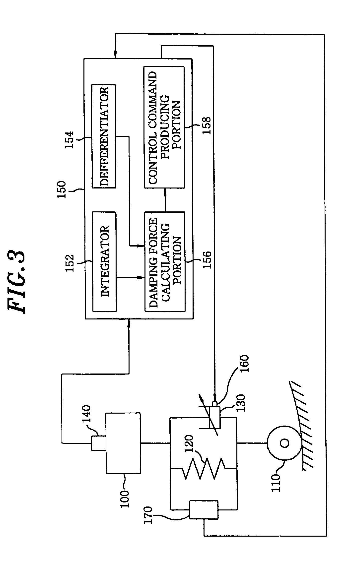
[0020]FIG. 3 is a block diagram of an electronically-controlled suspension apparatus in accordance with a first preferred embodiment of the present invention.

[0021] As shown in FIG. 3, the electronically-controlled suspension apparatus of the present invention includes a variable damper 130 installed between a vehicle body 100 and a wheel 110 (or wheel axle); and a second sensing device 170 for detecting vertical movements in up-and-down directions of the vehicle body 100 relative to the wheel 110, and generating a vehicle height signal indicating the detected vertical movements. A spring 120 is connected in parallel to the variable damper 130 and the second sensing device 170 at a location between the vehicle body 100 and the wheel 110, so that the spring 120 as well as the variable damper 130 supports the vehicle body 100. In FIG. 3, only one variabl...


PUM


Abstract

An electronically-controlled suspension apparatus includes a first sensing device for detecting a vertical acceleration of a vehicle body; a second sensing device for detecting vertical movements of a vehicle body relative to a wheel axle; and a controller for obtaining a vertical speed of the vehicle body by using the vertical acceleration detected by the first sensing device, obtaining a damper speed of a variable damper by using the vertical movements detected by the second sensing device, calculating a target damping force by using the vertical speed of the vehicle body and the damper speed, and determining a control command value by using the target damping force. The control command value is transmitted from the controller to the actuator of the variable damper to change damping force characteristics of the variable damper.

Description

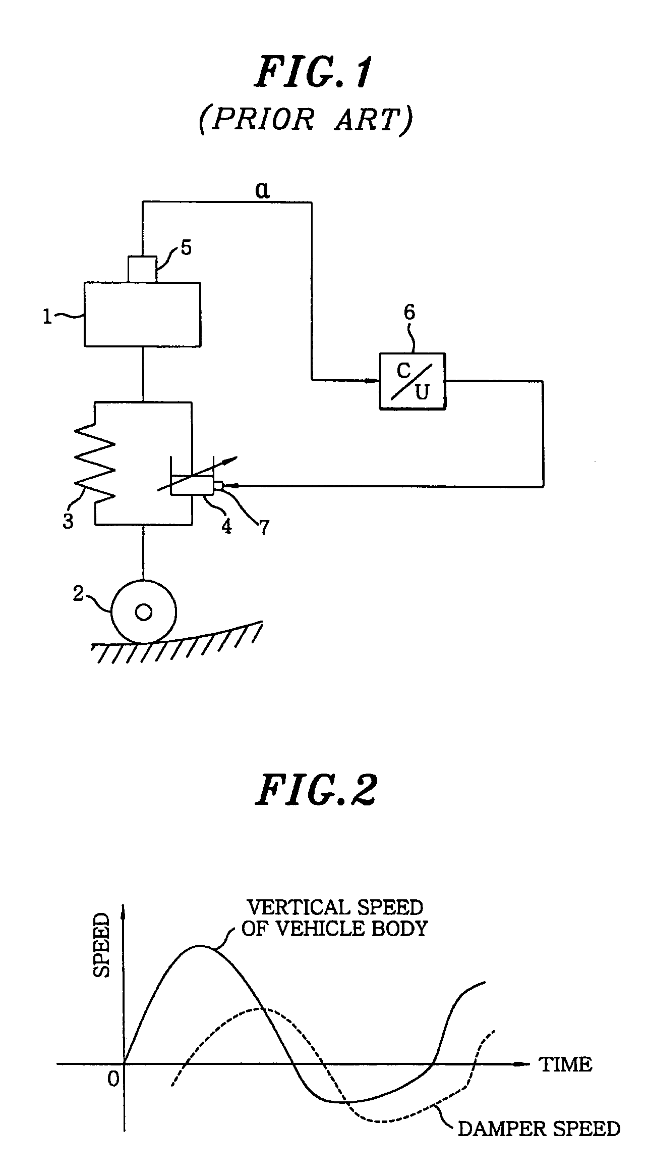
FIELD OF THE INVENTION [0001] The present invention relates to an electronically-controlled suspension apparatus and damping force control method; and more particularly, to an electronically-controlled suspension apparatus and damping force control method, which is capable of improving ride comfort and steering stability of a vehicle by controlling a damping force of a variable damper using not only a vertical speed of a vehicle body but also a damper speed of the variable damper. BACKGROUND OF THE INVENTION [0002] Referring to FIG. 1, there is presented a block diagram of a conventional electronically-controlled suspension apparatus. FIG. 2 displays graphs indicating a vertical speed of a vehicle body varying with time and a damper speed varying with time, respectively. [0003] As shown in FIG. 1, the conventional electronically-controlled suspension apparatus includes a variable damper 4 installed between a vehicle body 1 and a wheel 2 (or wheel axle). A spring 3 is connected in pa...

Claims


Application Information

Patent Timeline
IPC IPC(8): B60G17/015B60G17/0165B60G17/018B60G17/019B60G17/08
CPCB60G17/0165B60G17/018B60G17/08B60G2202/24B60G2400/102B60G2400/202B60G2800/916B60G2400/821B60G2500/10B60G2500/102B60G2600/184B60G2800/162B60G2400/252B60G17/015
Inventor KIM, WANIL
Owner HL MANDO CORP
Learn More