Method of displaying nodes and links

a node and link technology, applied in the field of connected graphs, can solve the problems of become extremely difficult to extract any useful information, and become difficult for the viewer to tell which links connect which nodes, so as to reduce complexity and not increase the complexity of the representation

Inactive Publication Date: 2005-05-26
RPX CLEARINGHOUSE
View PDF32 Cites 18 Cited by
  • Summary
  • Abstract
  • Description
  • Claims
  • Application Information

AI Technical Summary

Benefits of technology

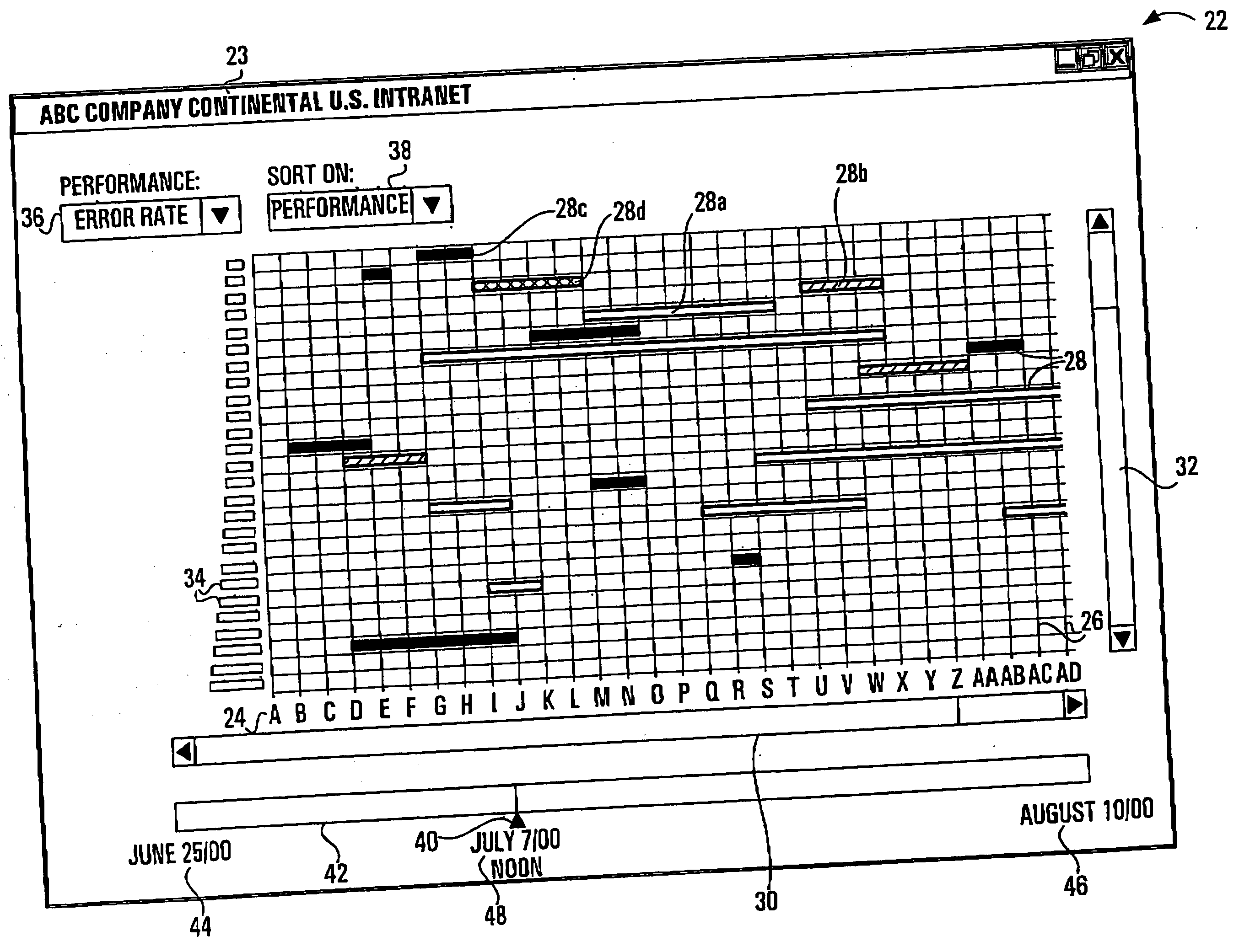
[0011] Advantageously, in representing the nodes as a series of parallel lines instead of points, the present invention provides a method of representing nodes and links in a clear, uncluttered manner. Furthermore, in applying the method of the present invention, the complexity of the representation does not increase as more nodes and links are added. Additionally, owing to the reduced complexity, the present method makes it possible for the representation to clearly communicate information about a link represented by a link line, by displaying the link line in a visually distinctive manner.

Problems solved by technology

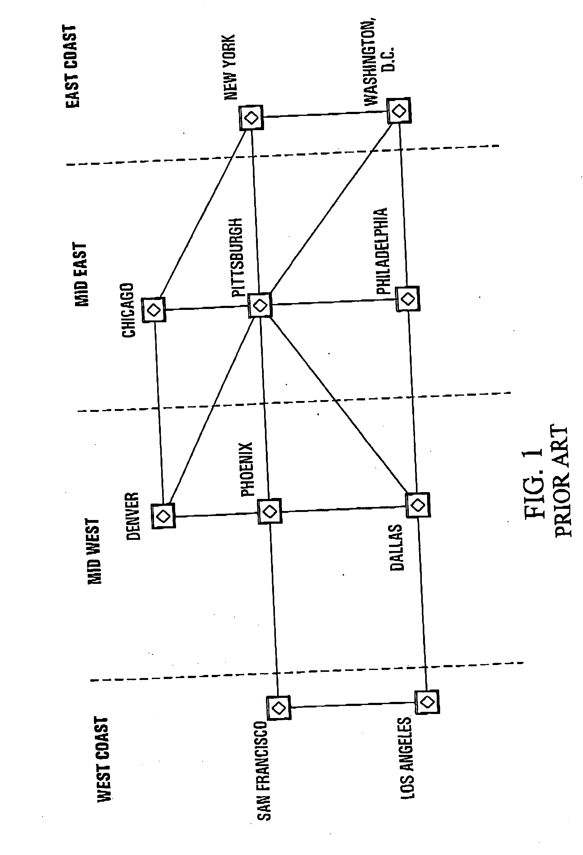
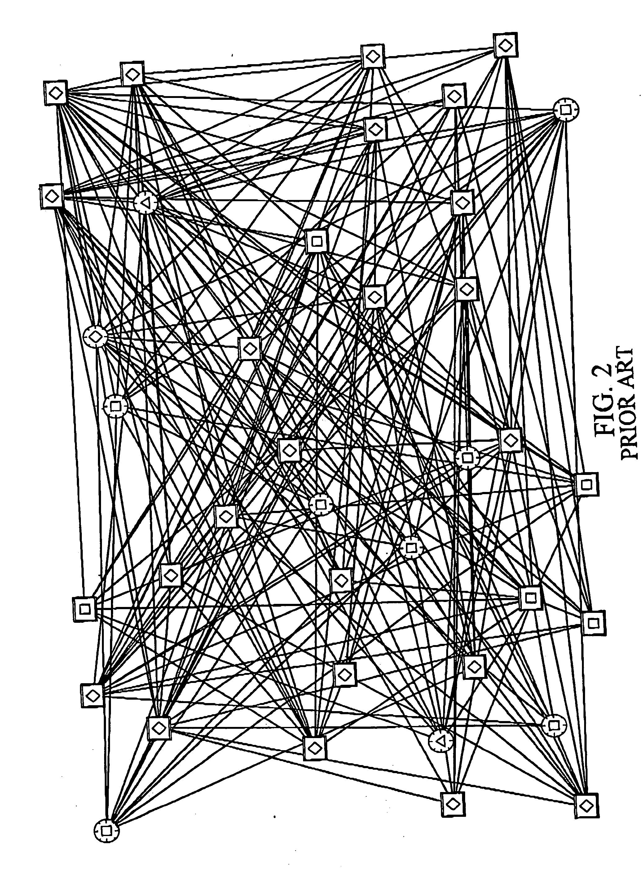
However, where there are either a large number of nodes, a large number of interconnections between the nodes, or some combination thereof, such a connected graph can become extremely complex such that it becomes impossible for the viewer to extract any useful information from it.
The representation of the links connecting the nodes become so dense that it forms a tight mesh, making it very difficult for the viewer to tell which links connect which nodes.
This problem is very common in telecommunication applications where there can be dozens or even hundreds of highly interconnected nodes in a given network.
However, these efforts provide only partial solutions since again, as the number of nodes and the interconnections between them increases, the graphs become, increasingly complex such that extracting any information from them becomes extremely difficult.
A further problem adding to the complexity of such graphs is introduced by telecommunication applications in which there are often several communication links between any two nodes.
However, such information is lost when the connected graph becomes complex.

Method used


Image

  • Method of displaying nodes and links
  • Method of displaying nodes and links
  • Method of displaying nodes and links

Examples


Embodiment Construction

[0027]FIG. 3 is a block diagram of a basic computer system suitable for implementing an embodiment of a method of the present invention. Node and link data 10, including such information as an identification of each node and link, as well as the nodes connected by each link, is stored in a memory storage device 11. When called upon to do so by a user, a processor 12 retrieves the node and link data 10 from the memory storage device 11, processes it as required, and displays the data on a display 13 in accordance with the present invention.

[0028] In FIG. 4, a flow chart for the implementation of an embodiment of a method of the present invention is shown. FIG. 5 shows a simple connected graph 14 created using the method described in the flow chart of FIG. 4.

[0029] In a first step 15, the processor 12 retrieves the node and link data 10 from the memory storage device 11. In a second step 16, the processor 12 processes this information as required, for example, determining the locati...


PUM


Abstract

The present invention relates to an improved method of displaying nodes, and links between nodes. Instead of the conventional method of displaying nodes and links as points and lines respectively, in accordance with the present invention, the nodes are each represented by parallel node lines. The links are then represented by link lines drawn perpendicular to the node lines, each of said link lines terminating at the node lines representing the nodes connected by the link represented by the link line. A graphical user interface incorporating this improved method of displaying nodes and links is also contemplated.

Description

FIELD OF THE INVENTION [0001] The invention relates to connected graphs, and in particular, to an improved method of displaying nodes, and links between nodes. BACKGROUND OF THE INVENTION [0002] A connected graph is any means of displaying a number of nodes (typically represented by points), and links (typically represented by lines between such points) connecting such nodes. Such connected graphs are used in mathematics to represent theoretical or real scenarios involving multiple nodes and the interconnections between them. In commercial applications, such graphs are used in industries such as the transportation industry to show transportation connections between cities, or subway stations for example, or in the telecommunications industry to display communication links between communication nodes. [0003] In typical connected graphs, the nodes are positioned geographically or logically, such that the position of such nodes provides some information to the viewer of the connected g...

Claims


Application Information

Patent Timeline
Patent Type & Authority Applications(United States)
IPC IPC(8): G06F3/00G06Q10/00
CPCG06T11/206G06Q10/08
Inventor BEAUDOIN, LUC
Owner RPX CLEARINGHOUSE
Why Eureka
Try Eureka